
Combining measurements from breathing rate sensors

Inactive Publication Date: 2008-01-15
OXFORD BIOSIGNALS
View PDF20 Cites 201 Cited by
  • Summary
  • Abstract
  • Description
  • Claims
  • Application Information

AI Technical Summary

Benefits of technology

[0002]The present invention relates to a method and apparatus for measuring the breathing rate of a subject, such as a human or animal, and in pa

Problems solved by technology

There is no clinically acceptable method for the non-invasive measurement of breathing rate.
A nasal thermistor provides a simple and inexpensive means of tracking respiration but it is obtrusive and is not deemed to be acceptable for patients on the general ward or even the Coronary Care Unit (CCU).
When monitored in a clinical environment, the impedance plethysmography (IP) signal is often very noisy and is seriously disrupted by patient movement or change in posture.
As a consequence, it has not been considered reliable enough to provide respiration information for regular use on the ward.
Unfortunately no amount of optimisation of the FIR low-pass filter characteristics will ever completely remove the cardiac-synchronous information which is occasionally very prominent.
So separating signal from noise on a fixed basis is impossible.
Similarly, the two major instances D, E of movement artefact in the PPG signal of FIGS. 5C and 5D at t=1770 and t=1920 cause erroneously low estimates of breathing rates at D′ and E′ because there is a significant delay between the last valid peak and the first peak after the movement artefact.

Method used


Image

  • Combining measurements from breathing rate sensors
  • Combining measurements from breathing rate sensors
  • Combining measurements from breathing rate sensors

Examples


Embodiment Construction

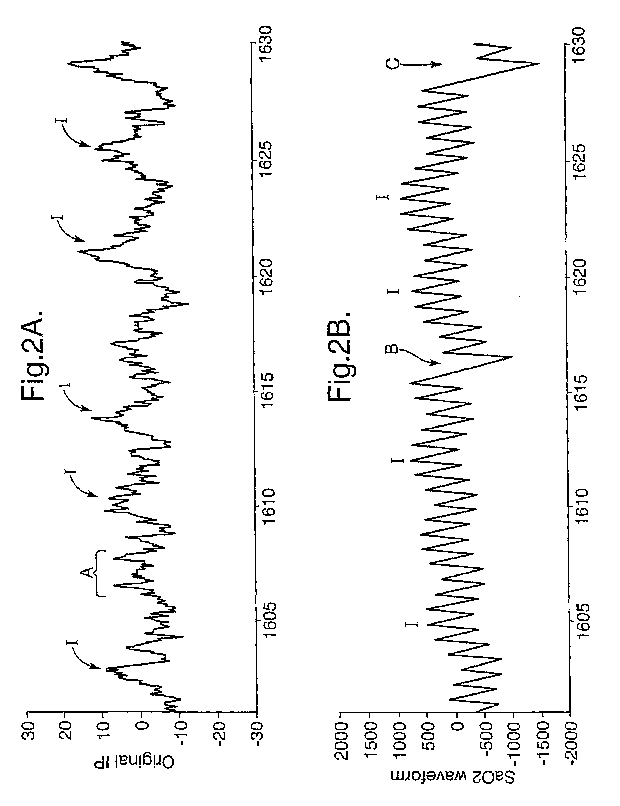
[0027]An embodiment of the invention will now be described in which the invention is applied in the medical field for the measurement of breathing rate using the two signals described above, namely the impedance pneumography and photoplethysmography signals. The results of applying this to the data of FIGS. 2 to 5 will be illustrated.

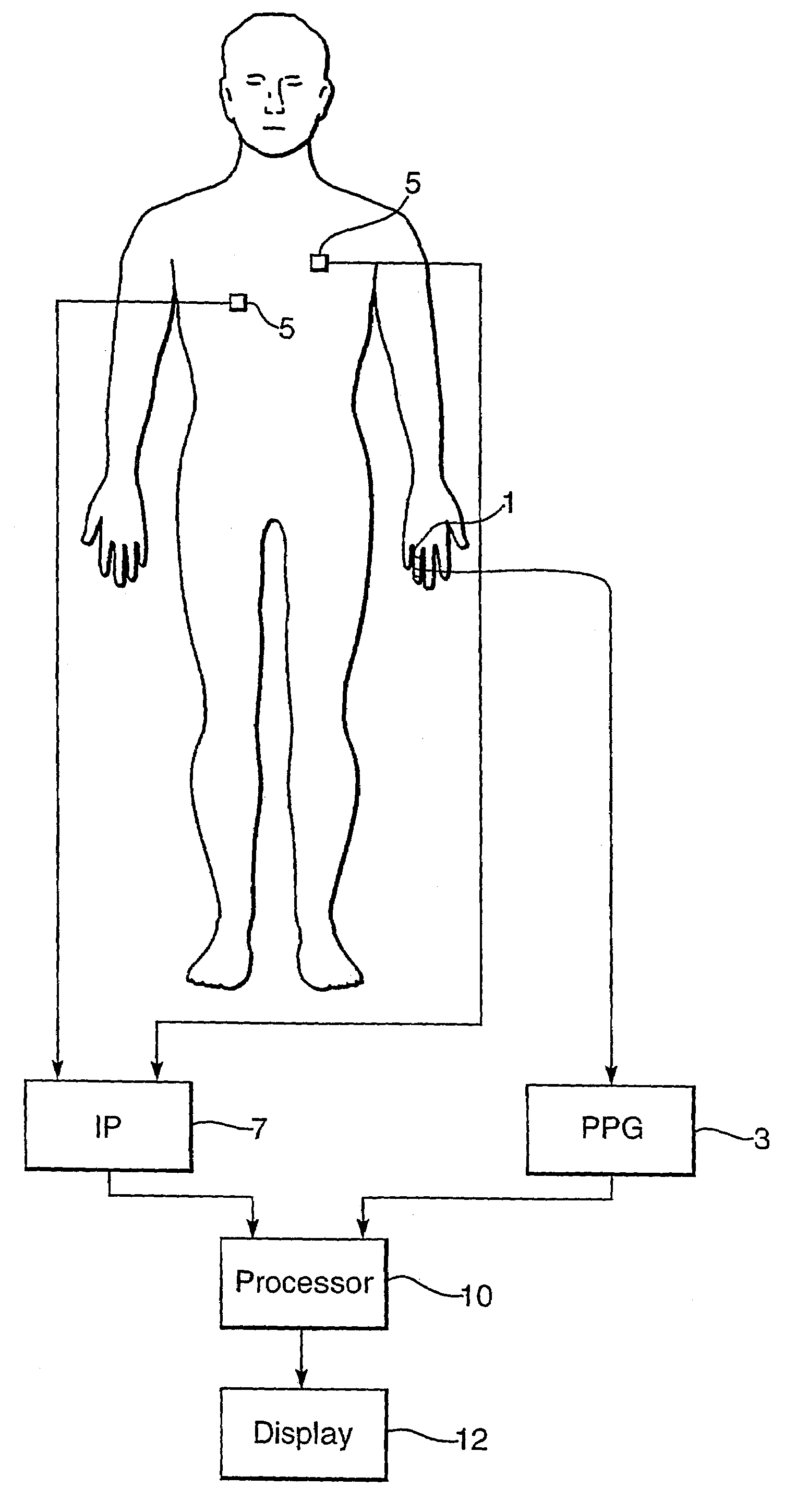
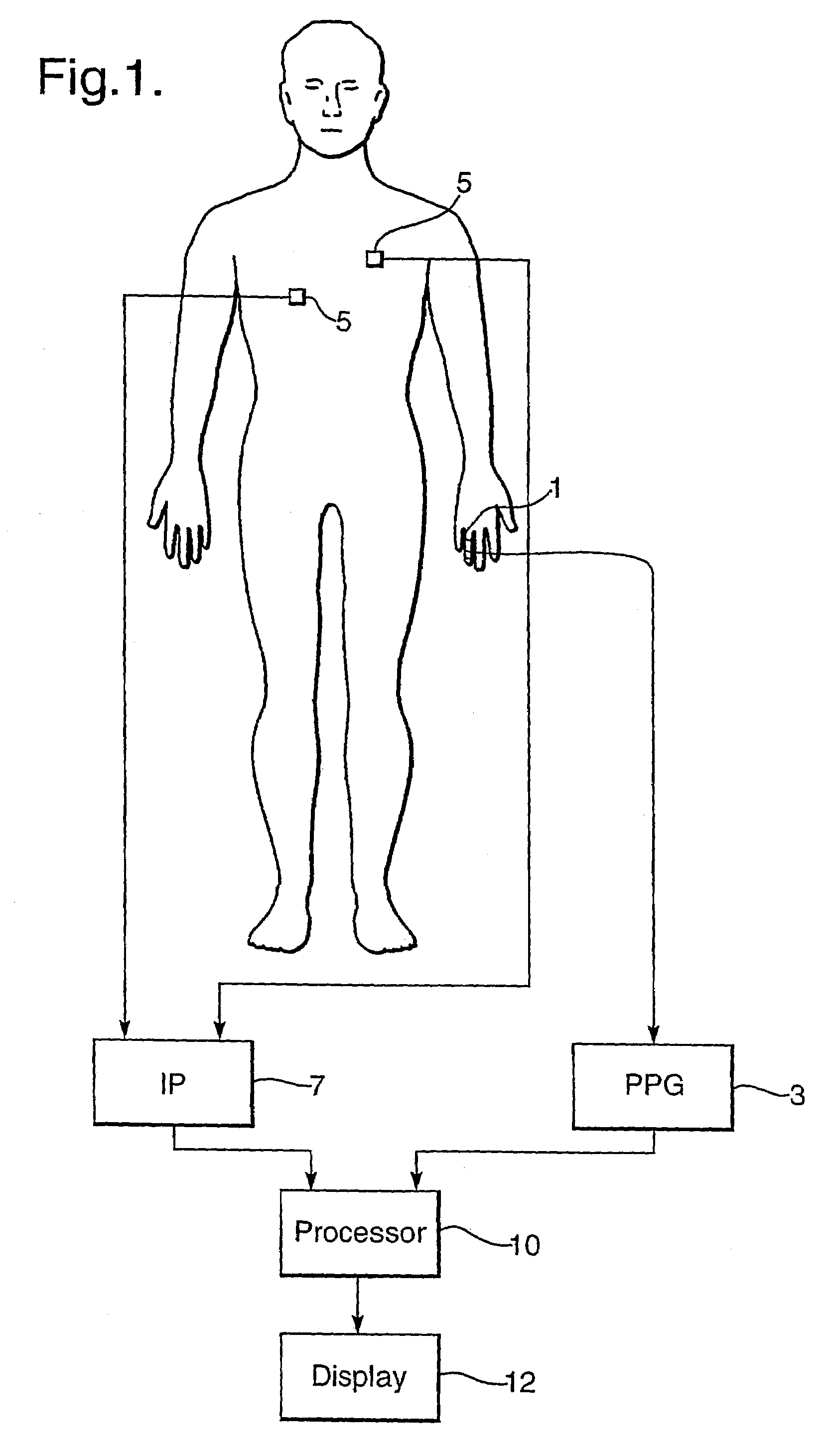
[0028]FIG. 1 schematically illustrates a breathing rate measurement apparatus in accordance with an embodiment of the invention. A PPG signal is obtained, as illustrated from a finger of a patient, though the signal can also be obtained from the earlobe, using a conventional PPG sensor 1 which is driven by and supplies its output to PPG apparatus 3. An IP signal is obtained by conventional IP equipment 7 using two electrodes 5 (though four electrodes may be used, with a pair for current injection and a pair for voltage measurement). The IP apparatus 7 and PPG apparatus 3 supply their signals to a processor 10 which processes the signals in the manner to...


PUM


Abstract

A method for combining breathing rate measurements from two or more independent measurement channels. Independent measurements of breathing rate, for instance by impedance pneumography and photoplethysmography, can be combined to derive an improved measurement eliminating artefacts on one channel. A model of the process generating the breathing rate, is constructed and is run independently for each channel to generate predictions of the breathing rate. The model may be a Kalman filter. The measured values are compared with the predicted values and the difference is used as an indication of the confidence in the measurement, the higher the difference the lower the confidence. The measurements from the two channels are combined using weights calculated from the respected differences.

Description

[0001]This application is the US national phase of international application PCT / GB02 / 05684 filed 13 Dec. 2002, which designated the US. PCT / GB02 / 05684 claims priority to GB Application No. 0130010.2 filed 14 Dec. 2001. The entire contents of these applications are incorporated herein by reference.BACKGROUND AND SUMMARY[0002]The present invention relates to a method and apparatus for measuring the breathing rate of a subject, such as a human or animal, and in particular to a way of combining measurements from two or more breathing rate sensors in order to provide an improved measurement of breathing rate.[0003]There is no clinically acceptable method for the non-invasive measurement of breathing rate. A nasal thermistor provides a simple and inexpensive means of tracking respiration but it is obtrusive and is not deemed to be acceptable for patients on the general ward or even the Coronary Care Unit (CCU). Electrical impedance plethysmography (also known as impedance pneumography) c...

Claims


Application Information

Patent Timeline
IPC IPC(8): A61B5/02A61B5/08
CPCA61B5/0816
Inventor TARASSENKO, LIONELMASON, CATHERINE LAURA
Owner OXFORD BIOSIGNALS
Learn More