Hydraulic accumulator

a technology of accumulators and accumulators, applied in the direction of machines/engines, transportation and packaging, brake systems, etc., can solve the problems of not meeting the requirements of an adequate degree of current hydraulic accumulators, adversely affecting the system, and not being able to effectively deter dirt particles, etc., to achieve the effect of improving the long-term operating behavior

Active Publication Date: 2008-01-29
HYDAC TECH GMBH
View PDF17 Cites 58 Cited by
  • Summary
  • Abstract
  • Description
  • Claims
  • Application Information

AI Technical Summary

Benefits of technology

[0007]An object of the present invention is to provide an improved hydraulic accumulator with a pressu

Problems solved by technology

Current hydraulic accumulators do not meet this requirement to an adequate degree.
Due to movement of the overall piston, these particles can lead to scratches which adversely affect the system.
In the known solution it is possible that when the piston moves, dirt particles which may have already c

Method used


Image

  • Hydraulic accumulator
  • Hydraulic accumulator
  • Hydraulic accumulator

Examples


Embodiment Construction

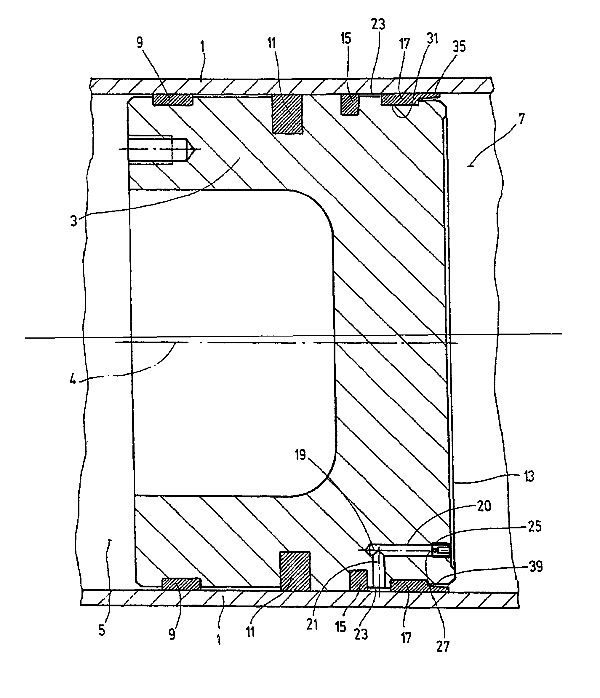
[0017]The exemplary embodiment of the hydraulic accumulator according to the present invention is in the form of a piston accumulator. FIG. 1 shows only the section of the accumulator housing 1 in which the piston 3 is located. It forms a separating element which can move in the axial direction, i.e., along the longitudinal axis 4, between the gas side 5 and the fluid side 7 of the accumulator housing 1.

[0018]In hydraulic accumulators incorporated into hydraulic systems, the gas side 5 is conventionally filled with nitrogen gas, while the fluid side 7 in operation conventionally contains hydraulic oil. The sealing and guidance system acts between the periphery of the piston 3 and the inside wall of the accumulator housing 1, prevents overflow of media from one piston side to the other piston side, and forms a piston guide when the piston 3 is moving. Such system has a plurality of components provided on the periphery of the piston 3. In succession, in FIG. 1 in the axial direction f...


PUM


Abstract

A hydraulic accumulator includes a piston (3) capable of moving in an accumulator housing (1) in its axial direction and separating a gas side (5) from a liquid side (7) of the accumulator housing (1). Guide elements (9, 17) designed to co-operate with the accumulator housing wall (1), as well as at least one sealing element (15), are arranged at the periphery of the piston. The sealing element is arranged offset in the axial direction relative to the guide elements (9, 17), and is located between the guide elements. In the piston (3), a pressure compensating channel (19) forms, at the piston periphery, a liquid flow path between the liquid side (7) and a space (2) located between the guide element (17) nearest to the liquid side (7) and the sealing element immediately next in the axial direction. A device (25) reducing the cross-section of the passage of the pressure compensating channel (19) is located in it.

Description

FIELD OF THE INVENTION[0001]The present invention relates to a hydraulic accumulator with a piston which can be moved in the accumulator housing in its axial direction and which separates the gas side from the fluid side of the accumulator housing. On the periphery of the piston, guide elements are provided for interaction with the wall of the accumulator housing. At least one sealing element, offset in the axial direction to the guide elements, is located in the peripheral section of the piston situated between the guide elements.BACKGROUND OF THE INVENTION[0002]Piston accumulators are commercially available and are widely used in hydraulic systems in a variety of applications. For example, they are used for storing energy, emergency actuation, leaking oil compensation, volume compensation, shock absorption, pulsation damping, and the like.[0003]Long-term behavior is of very great importance for economical and reliable use of these accumulators. To guarantee operating behavior whic...

Claims


Application Information

Patent Timeline
IPC IPC(8): F16L55/04F15B1/24
CPCF15B1/24F15B2201/205F15B2201/312F15B2201/3158
Inventor BALTES, HERBERT
Owner HYDAC TECH GMBH
Why Eureka
Try Eureka