Photosensor for a transmitted light method used for detecting the direction of movement of intensity maxima and intensity minima of an optical standing wave

a transmitted light and photosensor technology, applied in the direction of converting sensor output optically, instruments, semiconductor devices, etc., can solve the problems of high cost and application of considerable technological resources, and achieve the effect of eliminating the expensive adjustment of transparent photosensors

Inactive Publication Date: 2008-01-29
FORSCHUNGSZENTRUM JULICH GMBH
View PDF8 Cites 3 Cited by
  • Summary
  • Abstract
  • Description
  • Claims
  • Application Information

AI Technical Summary

Benefits of technology

[0013]The arrangement of at least two semiconductor components together on a substrate eliminates the expensive adjustment of the transparent photosensors. With two transparent photosensors produced on

Problems solved by technology

This requires the application of considerable technol

Method used


Image

  • Photosensor for a transmitted light method used for detecting the direction of movement of intensity maxima and intensity minima of an optical standing wave
  • Photosensor for a transmitted light method used for detecting the direction of movement of intensity maxima and intensity minima of an optical standing wave
  • Photosensor for a transmitted light method used for detecting the direction of movement of intensity maxima and intensity minima of an optical standing wave

Examples


Embodiment Construction

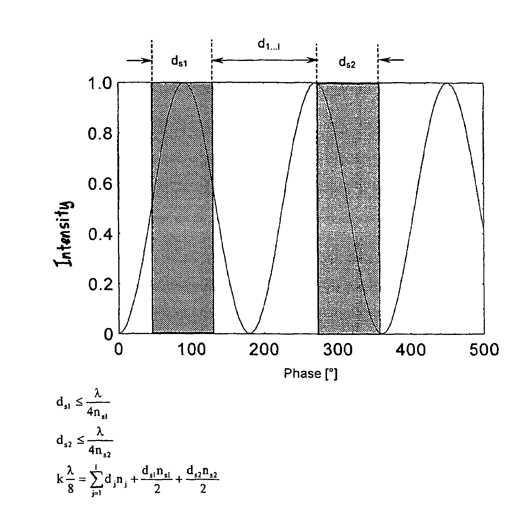
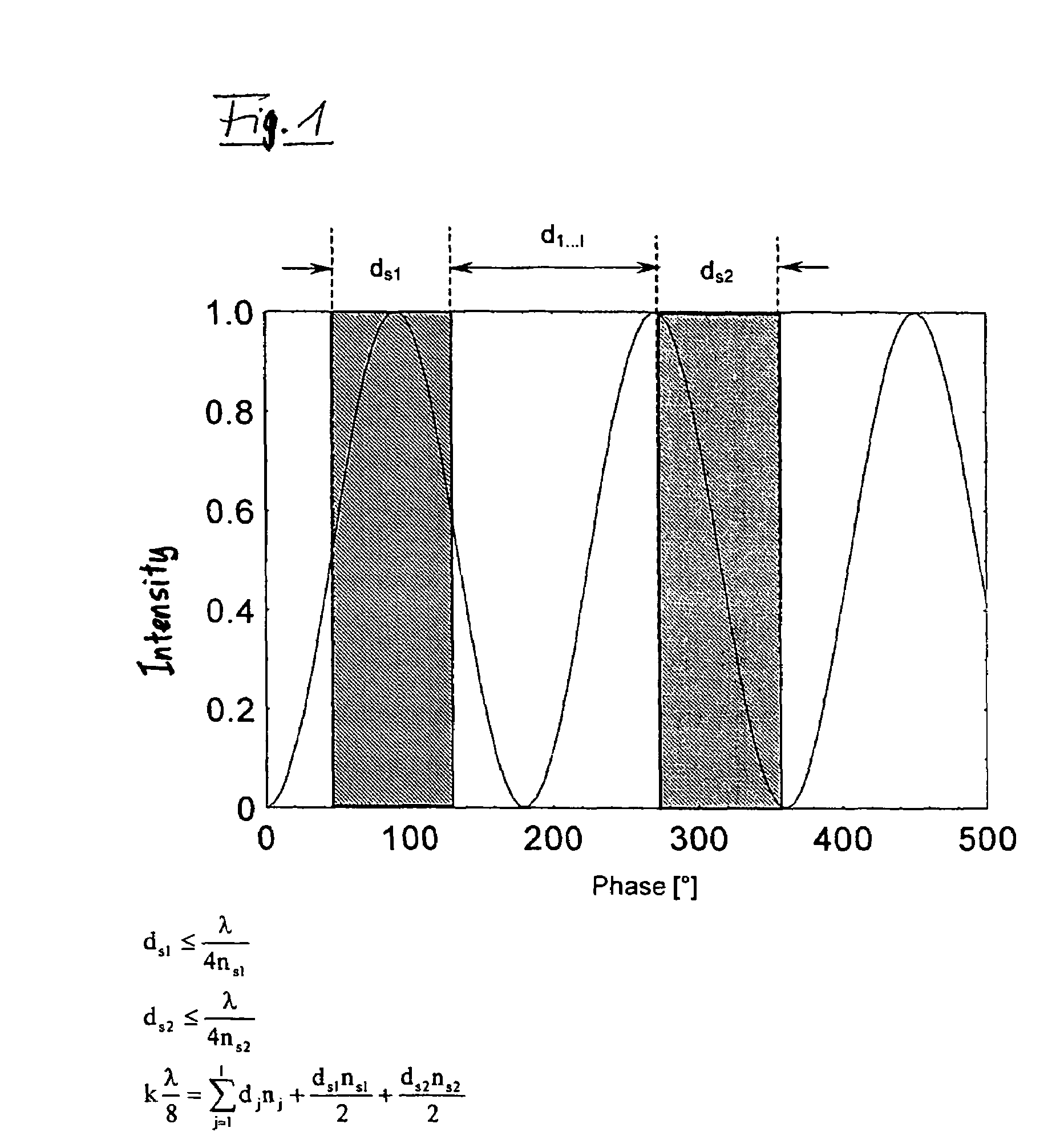
[0023]FIG. 1 shows a schematic diagram of the passage of a standing wave through a photosensor of the invention. The layer thickness of the photoelectrically active layers ds1 and ds2 is

[0024]ds1≤λ4⁢⁢ns1Equation⁢⁢1ds2≤λ4⁢ns2Equation⁢⁢2

where ns1 and ns2 are the indices of refraction of the photoactive layers ds1 and ds2. In general, the phase condition may be described as modified

[0025]∑j=1l⁢nj⁢dj=k⁢λ8-ds1⁢ns12-ds2⁢ns22Equation⁢⁢3

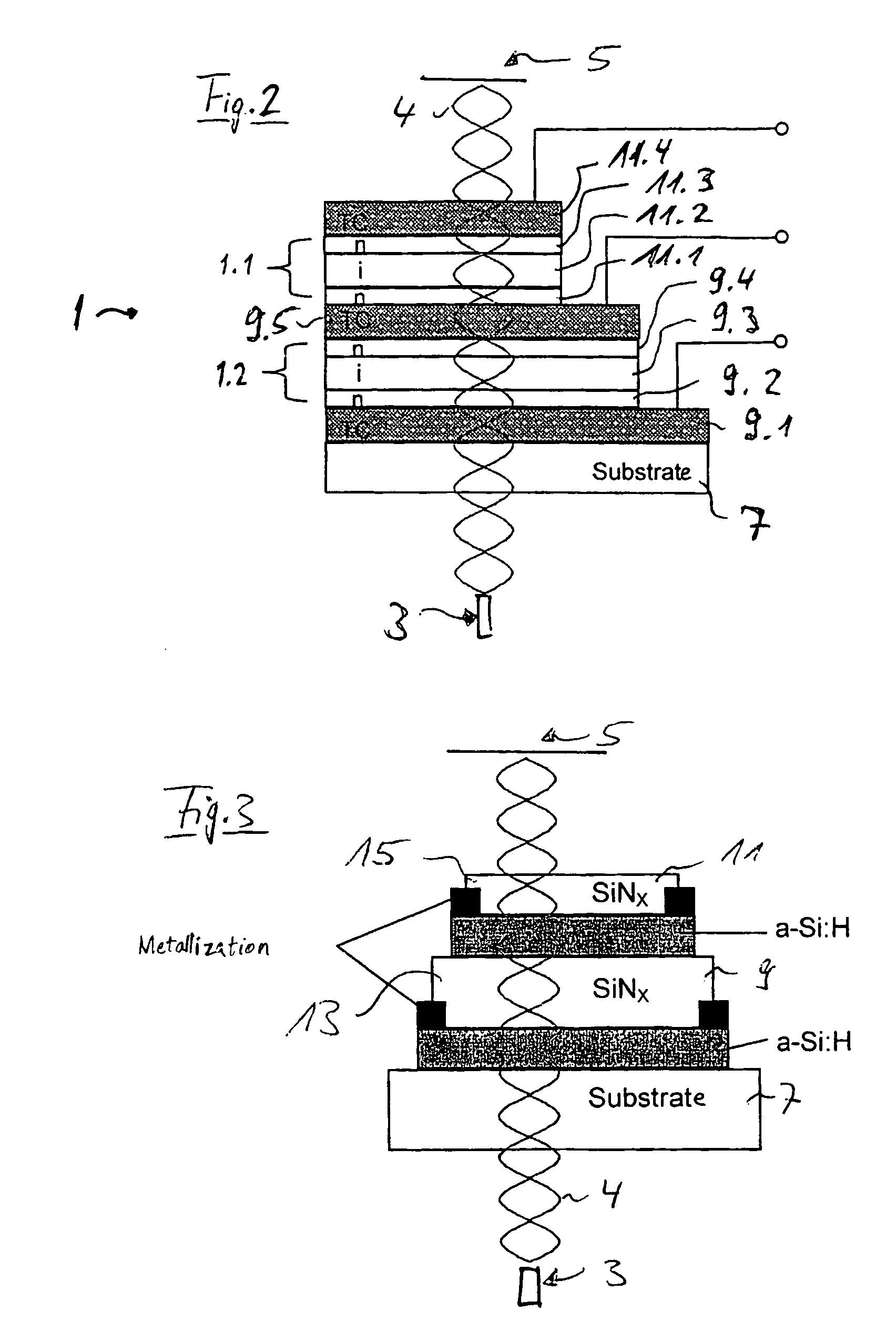
[0026]FIG. 2 shows a cross section of a photosensor 1 of the invention, to which the diagram of FIG. 1 is to be applied. The photosensor 1 is arranged between a radiation source 3 and a mirror 5. This arrangement is set up in such a way that the optical axis of a standing wave 4 produced by the radiation source 3 passes perpendicularly through the thickness of the photosensor 1 and is perpendicularly incident on the mirror. The photosensor 1 comprises a substrate 7, which may be composed of glass, quartz, or plastic. If a plastic substrate is selected, it ma...


PUM


Abstract

A photosensor for a transmitted-light method for detecting the intensity profile of an optical standing wave, with a transparent substrate, with a semiconductor component, and with at least three contacts, is characterized by the fact that two semiconductor components are connected with each other, such that the first semiconductor component and the second semiconductor component each have a photoelectrically active first semiconductor layer, and such that the two photoelectrically active semiconductor layers have a fixed phase relation to each other, which is adjusted by at least one photoelectrically inactive layer.

Description

PRIORITY CLAIM[0001]This is a U.S. national stage of application No. PCT / DE02 / 02135, filed on 12 Jun. 2002. Priority is claimed on that application and on the following application(s): Country: Germany, Application No.: 101 31 608.9, Filed: 29 Jun. 2001.BACKGROUND OF THE INVENTION[0002]1. Field of the Invention[0003]The invention concerns a photosensor for a transmitted-light method for detecting the direction of movement of the intensity maxima and intensity minima in an intensity profile, with a transparent substrate, two first semiconductor components assigned to the substrate, and at least three contacts.[0004]2. Description of the Prior Art[0005]In the field of photoelectric detection of visual radiation, photosensors that operate by a wide variety of principles are used, e.g., as photoresistors, photodiodes, phototransistors, or the like. A common feature of all of these designs is that the visual radiation is detected by the incident-light method. Typical applications for the...

Claims


Application Information

Patent Timeline
IPC IPC(8): H01L31/075H01L31/10G01B9/02G01D5/26H01L31/0248H01L31/109
CPCG01D5/266H01L31/109Y02E10/548
Inventor KNIPP, DIETMARSTIEBIG, HELMUTBUCHNER, HANS-JOACHIMJAGER, GERD
Owner FORSCHUNGSZENTRUM JULICH GMBH
Why Eureka
Try Eureka