Method and circuit for measuring capacitance and capacitance mismatch

a capacitance mismatch and capacitance technology, applied in the field of measurement methods and circuits, can solve problems such as too complex measurement to be enabled, and achieve the effect of enhancing measurement efficiency and effectively reducing the area of circuit layou

Active Publication Date: 2008-01-29
UNITED MICROELECTRONICS CORP
View PDF4 Cites 82 Cited by
  • Summary
  • Abstract
  • Description
  • Claims
  • Application Information

AI Technical Summary

Benefits of technology

[0028]Accordingly, in the present invention, the first switches, the second switches and the third switches are provided for selecting the first capacitor and the second capacitor to be measured, wherein the precision of the measurement result is not influenced by all the switches. In addition, in the present invention, only four pads and one P-type transistor is sufficient, thus the area of the layout of the circuit is effectively reduced. In addition, when a selection circuit such as a shift register is provided, the measurement can be programmed and can be automatic, and thus the efficiency of the measurement is enhanced.

Problems solved by technology

Thus, if the conventional capacitor matching circuit and method are provided for a semiconductor integrated circuit (IC), the measurement too complex to be enabled.

Method used


Image

  • Method and circuit for measuring capacitance and capacitance mismatch
  • Method and circuit for measuring capacitance and capacitance mismatch
  • Method and circuit for measuring capacitance and capacitance mismatch

Examples


Embodiment Construction

[0037]The present invention now will be described more fully hereinafter with reference to the accompanying drawings, in which preferred embodiments of the invention are shown. This invention may, however, be embodied in many different forms and should not be construed as limited to the embodiments set forth herein; rather, these embodiments are provided so that this disclosure will be thorough and complete, and will fully convey the scope of the invention to those skilled in the art. Like numbers refer to like elements throughout.

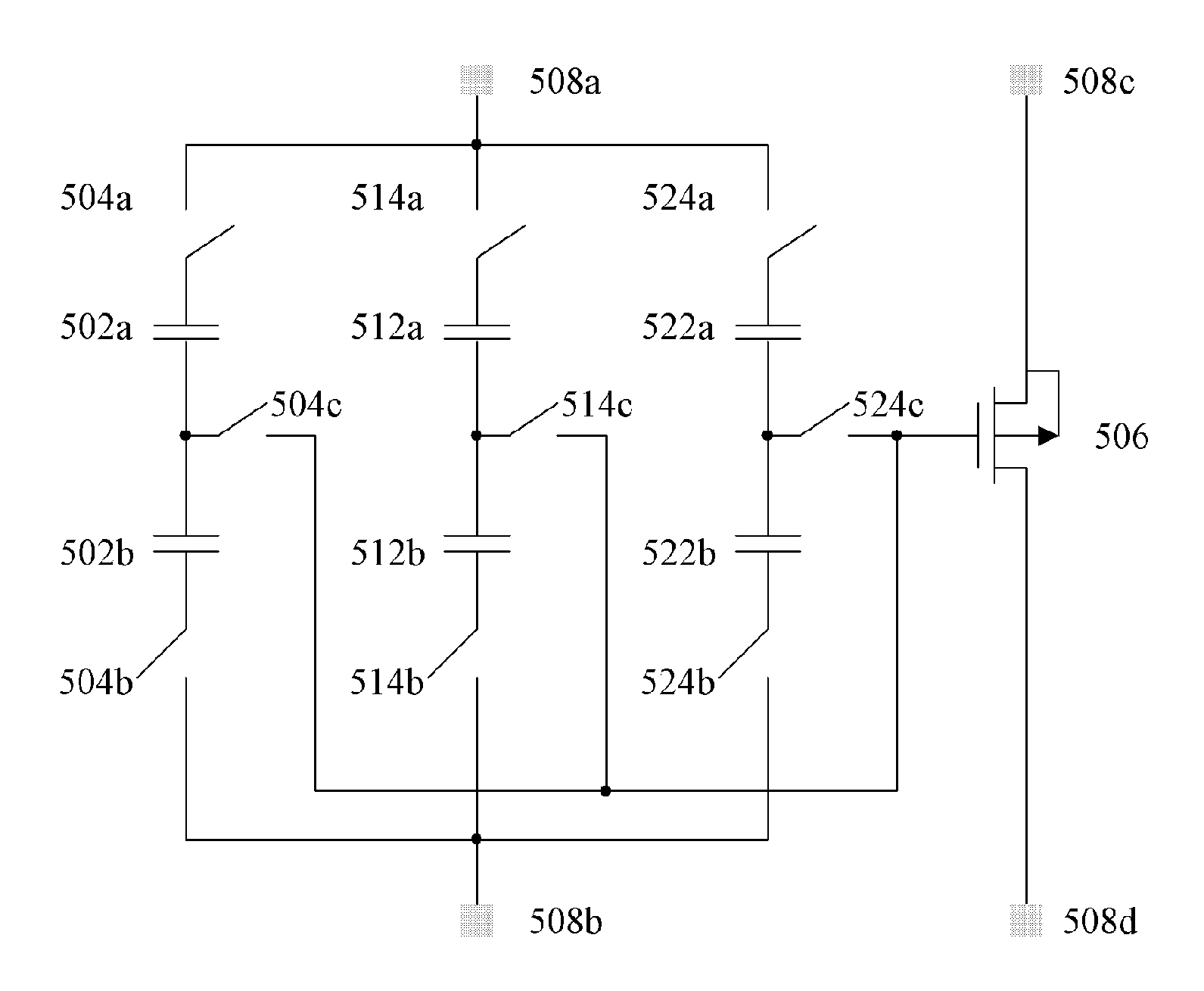
[0038]FIG. 5 illustrates a circuit for measuring a capacitance and a differential capacitance of two capacitors according to one embodiment of the present invention. It is noted that FIG. 5 illustrates three capacitor pairs, however, the scope of present invention is not limited to the drawings and the embodiments of the invention. Referring to FIG. 5, a circuit for measuring at least two capacitor pairs comprises, for example but not limited to, a first, ...


PUM

PropertyMeasurementUnit
capacitanceaaaaaaaaaa
capacitancesaaaaaaaaaa
capacitor matching methodaaaaaaaaaa

Abstract

A circuit and method for measuring capacitance and capacitance mismatch of at least one capacitor pair are provided. The circuit includes a first switch, a second switch, a third switch and a P-type transistor. A terminal of the first switch is connected to a terminal of a first capacitor, and a terminal of the second switch is connected to a terminal of a second capacitor. A terminal of the third switch is connected to another terminal of the first capacitor and another terminal of the second capacitor, and a gate of the P-type transistor is connected to another terminal of the third switch. When the first, second and third switches are turned on, a capacitance of the first capacitor, a capacitance of the second capacitor, or a capacitance mismatch between the first and second capacitances is measured.

Description

BACKGROUND OF THE INVENTION[0001]1. Field of the Invention[0002]The present invention generally relates to a measurement method and circuit. More particularly, the present invention relates to a measurement method and circuit for measuring the capacitance and the capacitance mismatch of capacitor pairs.[0003]2. Description of Related Art[0004]Conventionally, in a semiconductor integrated circuit (IC), capacitor is an important component. In general, the statistic variation of the mismatch (or ratio) of the capacitances of capacitor pair is important for switched capacitor circuit techniques. Therefore, the measurement of the mismatch or the ratio of the capacitances of capacitor pair is highly desired.[0005]In general, for a capacitor pair constructed by two capacitors, a conventional measurement method is provided by a capacitor matching method to measure the mismatch between the capacitances of two capacitors. FIG. 1 illustrates a conventional circuit for measuring a capacitance a...

Claims


Application Information

Patent Timeline
Patent Type & Authority Patents(United States)
IPC IPC(8): G01R31/08G01R31/02
CPCG01R27/2605G01R31/318533
Inventor KUO, SHU-HUALI, JUI-TING
Owner UNITED MICROELECTRONICS CORP
Why Eureka
Try Eureka