
Coarse frequency synchronization method and apparatus in OFDM system

a frequency synchronization and coarse frequency technology, applied in orthogonal multiplexing, multiplex communication, amplitude demodulation, etc., can solve the problems of method requiring a considerable amount of computation and excessive time delay, and achieve stable frequency synchronization with a small amount of computation

Active Publication Date: 2008-01-29
SAMSUNG ELECTRONICS CO LTD
View PDF13 Cites 8 Cited by
  • Summary
  • Abstract
  • Description
  • Claims
  • Application Information

AI Technical Summary

Benefits of technology

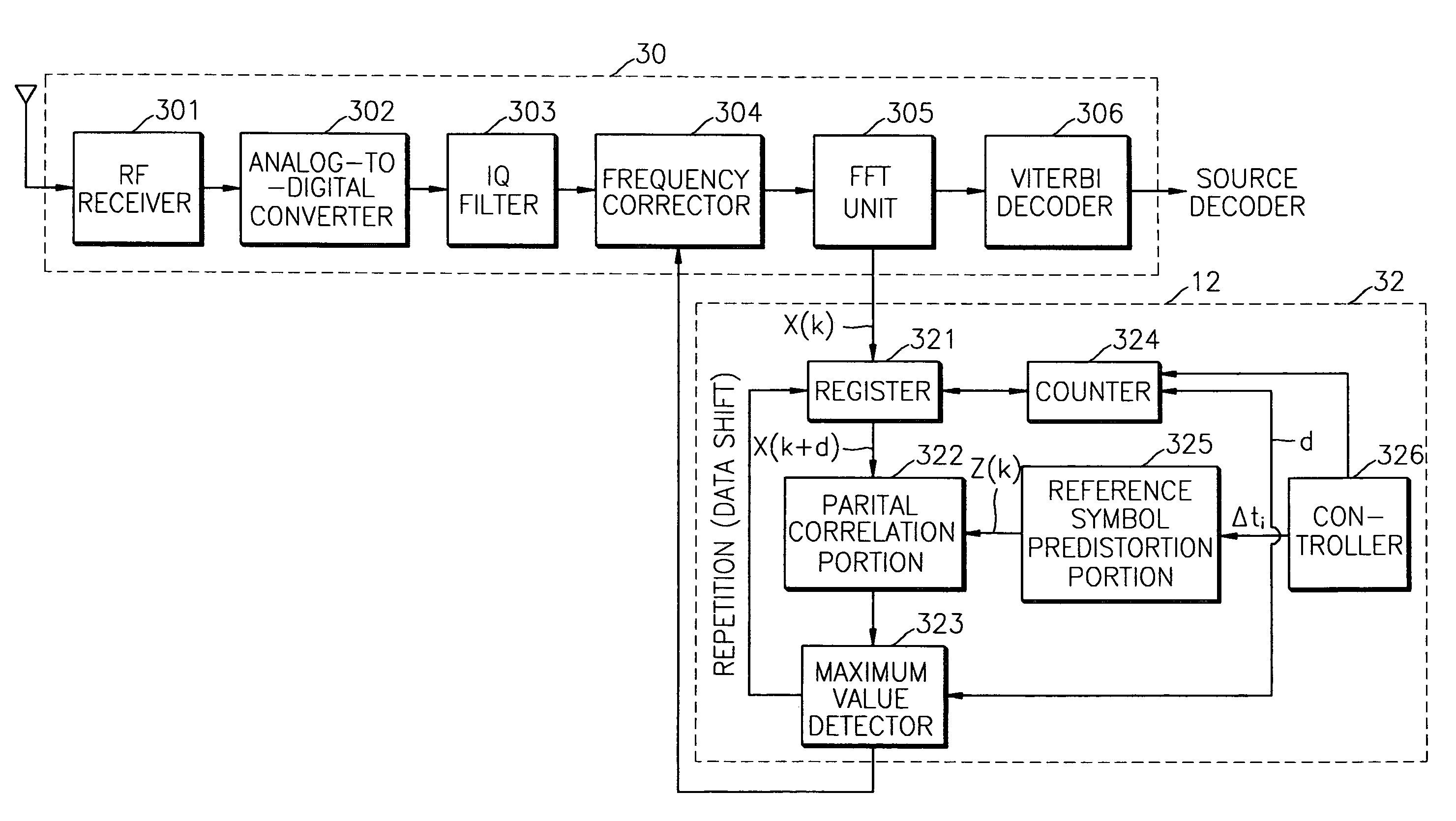
The present invention provides a coarse frequency synchronization apparatus and method for an OFDM receiver that can perform stable frequency synchronization with a small amount of computation. The apparatus includes a buffer, controller, reference symbol predistortion portion, counter, partial correlation portion, and maximum value detector. The method involves receiving a demodulated symbol, outputting a shifted symbol, determining the length of a summation interval, generating a reference symbol with distorted phase, calculating partial correlation values for each sub-band, and determining the shift amount as the estimated coarse frequency offset value. The technical effect of this invention is to enable accurate and efficient frequency synchronization in an OFDM receiver.

Problems solved by technology

However, this method requires a considerable amount of computation.
Specifically, this method requires a very complicated IFFT module in order to accurately estimate a frequency error, and causes an excessive time delay due to a long response time.

Method used


Image

  • Coarse frequency synchronization method and apparatus in OFDM system
  • Coarse frequency synchronization method and apparatus in OFDM system
  • Coarse frequency synchronization method and apparatus in OFDM system

Examples


Embodiment Construction

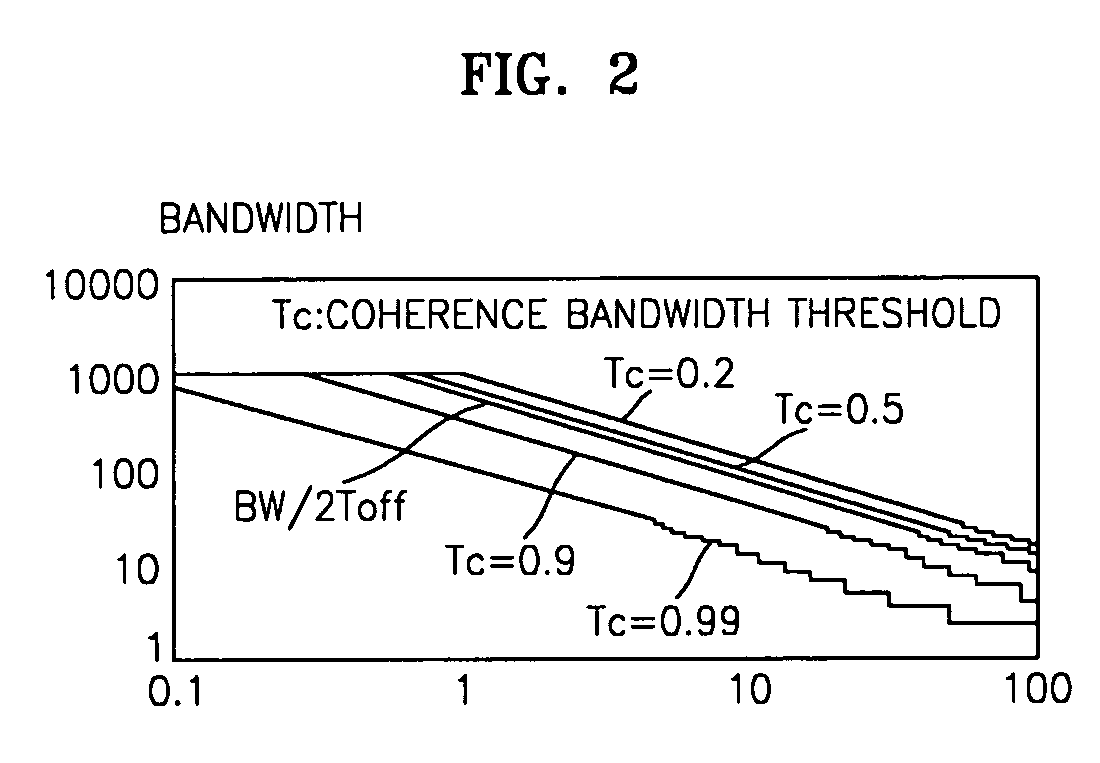
[0032]To aid in understanding a coarse frequency apparatus and method according to the present invention, a correlation value and a phase coherence bandwidth applied in accordance with this invention will now be described.

[0033]First, to identify the effect of carrier frequency offset of a reception signal, it is assumed that the k-th subcarrrier reception frequency of the reception signal is fk+fOff where fk and foff denote a subcarrier frequency and a frequency offset, respectively. A frequency offset value is measured in units of a multiple of spacing of subcarrier frequency. In general, integer and decimal multiples of subcarrier spacing are separately processed. Thus, each term of fk+foff is defined as follows:

[0034]fk=kTsfoff=Δ⁢⁢f·1Ts=(Δ⁢⁢fi+Δ⁢⁢ff)·1Ts,(4)

where Δf denotes a number that represents the frequency offset of subcarrier by a multiple of subcarrier spacing and can also be replaced by the sum of an integer Δfi and a decimal Δff that satisfies the condition −½f<½. Give...


PUM


Abstract

An apparatus and method for performing coarse frequency synchronization in an orthogonal frequency division multiplexing (OFDM) receiver are provided. The coarse frequency synchronization apparatus in a frequency synchronizer of an orthogonal frequency division multiplexing (OFDM) receiver includes a buffer that receives a demodulated symbol and outputs a shifted symbol generated by cyclically shifting the symbol by a predetermined shift amount; a controller that determines the length of an summation interval according to a phase coherence bandwidth and a number of sub-bands into which the summation interval is divided, and generates and adjusts a symbol time offset according to the number of sub-bands; a reference symbol predistortion portion that generates a reference symbol whose phase is distorted by the symbol time offset; a counter that counts the shift amount; a partial correlation portion that receives the shifted symbol and the reference symbol and calculates a partial correlation value for each of the sub-bands; and a maximum value detector that calculates the shift amount where the partial correlation value is a maximum and outputs the same as an estimated coarse frequency offset value.

Description

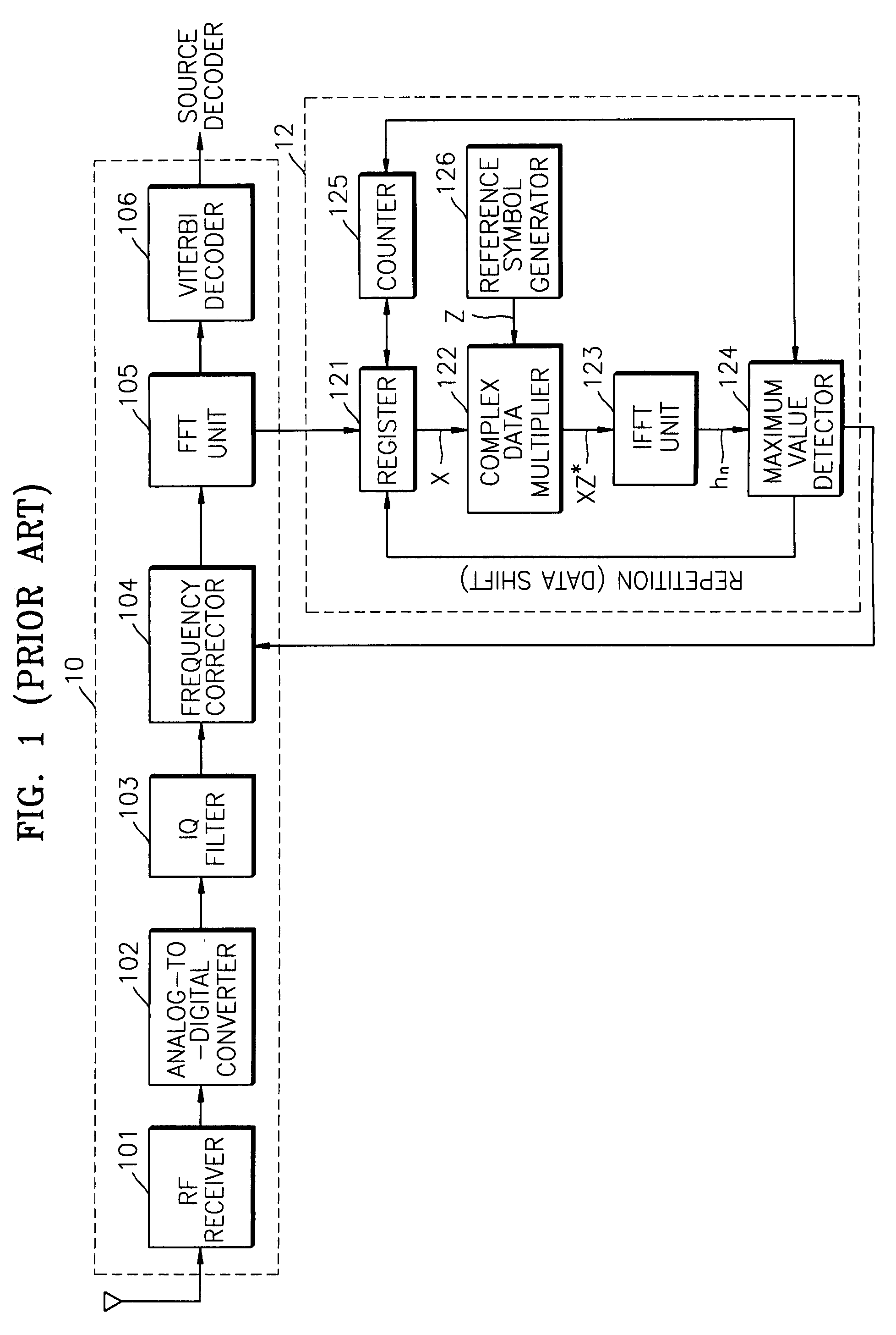
CROSS REFERENCE TO RELATED APPLICATIONS[0001]This application claims priority from Korean Patent Application No. 2003-16287, filed Mar. 15, 2003, the contents of which are incorporated herein by reference in their entirety.BACKGROUND OF THE INVENTION[0002]1. Field of the Invention[0003]The present invention relates to a coarse frequency synchronization method and apparatus for an orthogonal frequency division multiplexing (OFDM)—based system, and more particularly, to a coarse frequency synchronization method and apparatus in an OFDM receiver.[0004]2. Description of the Related Art[0005]FIG. 1 is a block diagram showing the structure of a conventional OFDM receiver system. Referring to FIG. 1, the conventional OFDM receiver system includes an OFDM demodulator 10 and a frequency synchronizer 12. The OFDM demodulator 10 includes a RF receiver 101, an analog-to-digital converter 102, an I / Q filter 103, a frequency corrector 104, an FFT unit 105, and a Viterbi decoder 106. The frequency...

Claims


Application Information

Patent Timeline
Patent Type & Authority Patents(United States)
IPC IPC(8): H04K1/10H04J11/00H04L27/06H04L7/00H04L27/26
CPCH04L27/2659H04L27/2675H04L7/00
Inventor KIM, KWANG-CHUL
Owner SAMSUNG ELECTRONICS CO LTD
Learn More