Utensil cooling device

a cooling device and utensil technology, applied in the field of utensil cooling devices, can solve the problems of individual dropping the device, damage to the device, and high repair and replacement costs, and achieve the effect of effectively conducting heat and convenient drawing hea

Inactive Publication Date: 2008-02-05
HENDERSON ANTHONY C +1
View PDF16 Cites 2 Cited by
  • Summary
  • Abstract
  • Description
  • Claims
  • Application Information

AI Technical Summary

Benefits of technology

[0013]The body includes spaced inner and outer layers defining a gap therebetween and extending about a perimeter of the device. The device may further include a flexible heat-absorbing layer disposed within the gap for conveniently drawing heat away from the cavity and may include a copper wire mesh coated along an inner surface of the cavity for effectively conducting heat away from the electric hairstyling scissors disposed therein. A power cord is provided for coupling the body to an external power source.
[0014]The present invention further includes a combination fan and vent electrically coupled to the power source and disposed within the body. Such a combined unit advantageously evacuates heated air through the vent. A thermoelectric cooler is electrically coupled to the power source, and is disposed within the body. Such a cooler may include conventional cooling devices, well known to a person of ordinary skill in the art.
[0015]The present invention also includes a plurality of elongated tubes having opposed end portions connected to the cooler and the cavity respectively. Air that has a first temperature is drawn to the cooler via one of the plurality of tubes and air that has a second temperature is introduced to the cavity via another the plurality of tubes wherein the first air temperature is preferably higher than the second air temperature.

Problems solved by technology

A common problem that occurs with devices such as electrical hair clippers is heat generated by the movable blades, due to friction, and heat generated from the electrical current used to power such devices.
This heat can inconveniently be transferred to the hands of the person using the device, resulting in sweating, that can lead to the individual dropping the device.
Damage is thus inflicted to the device which is costly to repair and costly to replace.
Another problem is when the heat generated in the cutting blades is transferred to the individual whose hair is being cut.
Such transferred heat can cause inconvenient burns and general discomfort during the hair cut, which could lead to the individual not returning to that particular hair dresser in the future.
When the hair cutting device overheats, time must be taken to wait for that device to cool down again before another hair cut can be administered with it.
This will result in lost revenue for the hair dresser, or cause the hair dresser to inconveniently have to purchase more than one of the same hair cutting devices.

Method used


Image

  • Utensil cooling device
  • Utensil cooling device
  • Utensil cooling device

Examples


Embodiment Construction

[0022]The present invention will now be described more fully hereinafter with reference to the accompanying drawings, in which a preferred embodiment of the invention is shown. This invention may, however, be embodied in many different forms and should not be construed as limited to the embodiment set forth herein. Rather, this embodiment is provided so that this application will be thorough and complete, and will fully convey the true scope of the invention to those skilled in the art. Like numbers refer to like elements throughout the figures.

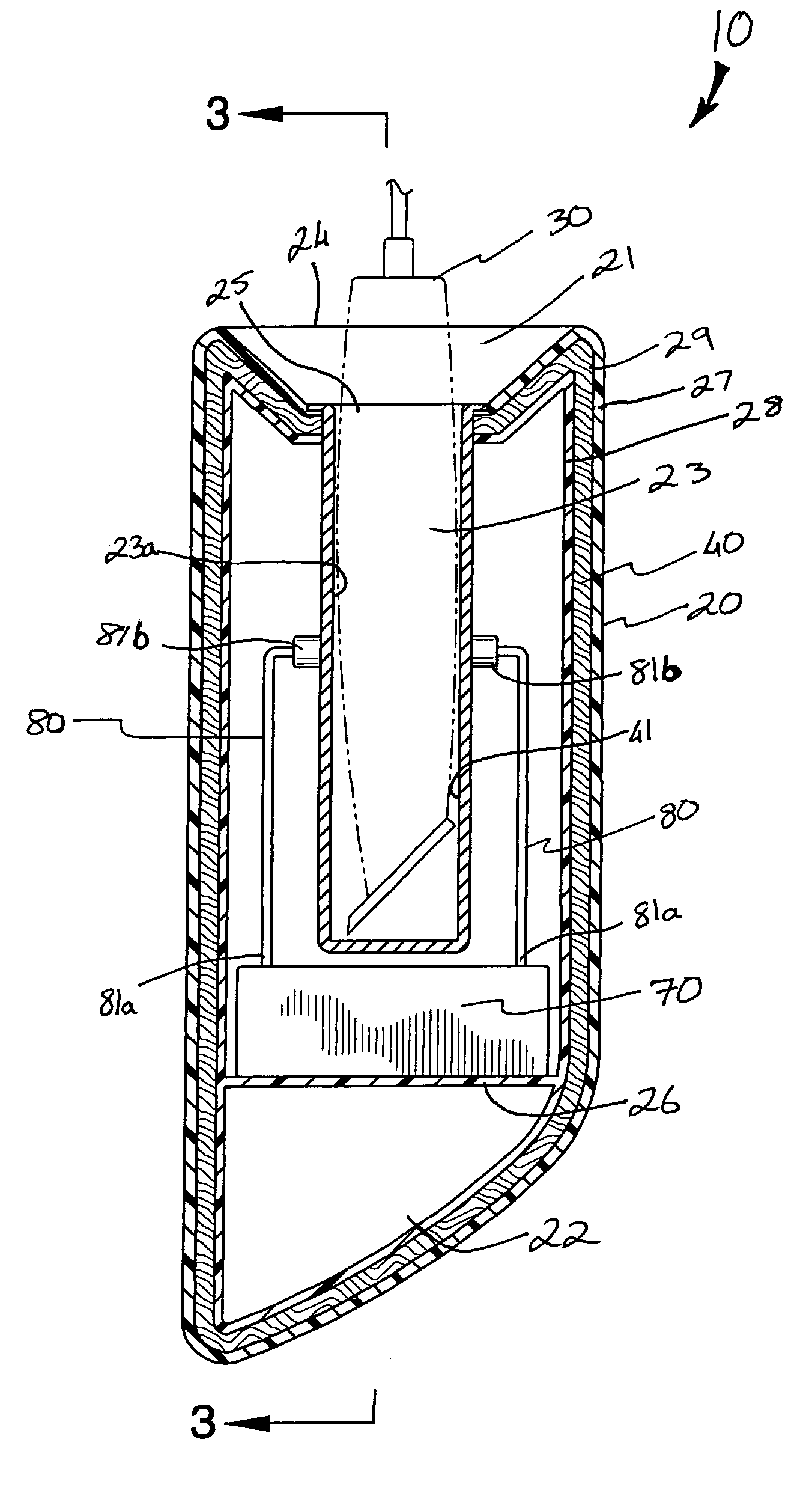
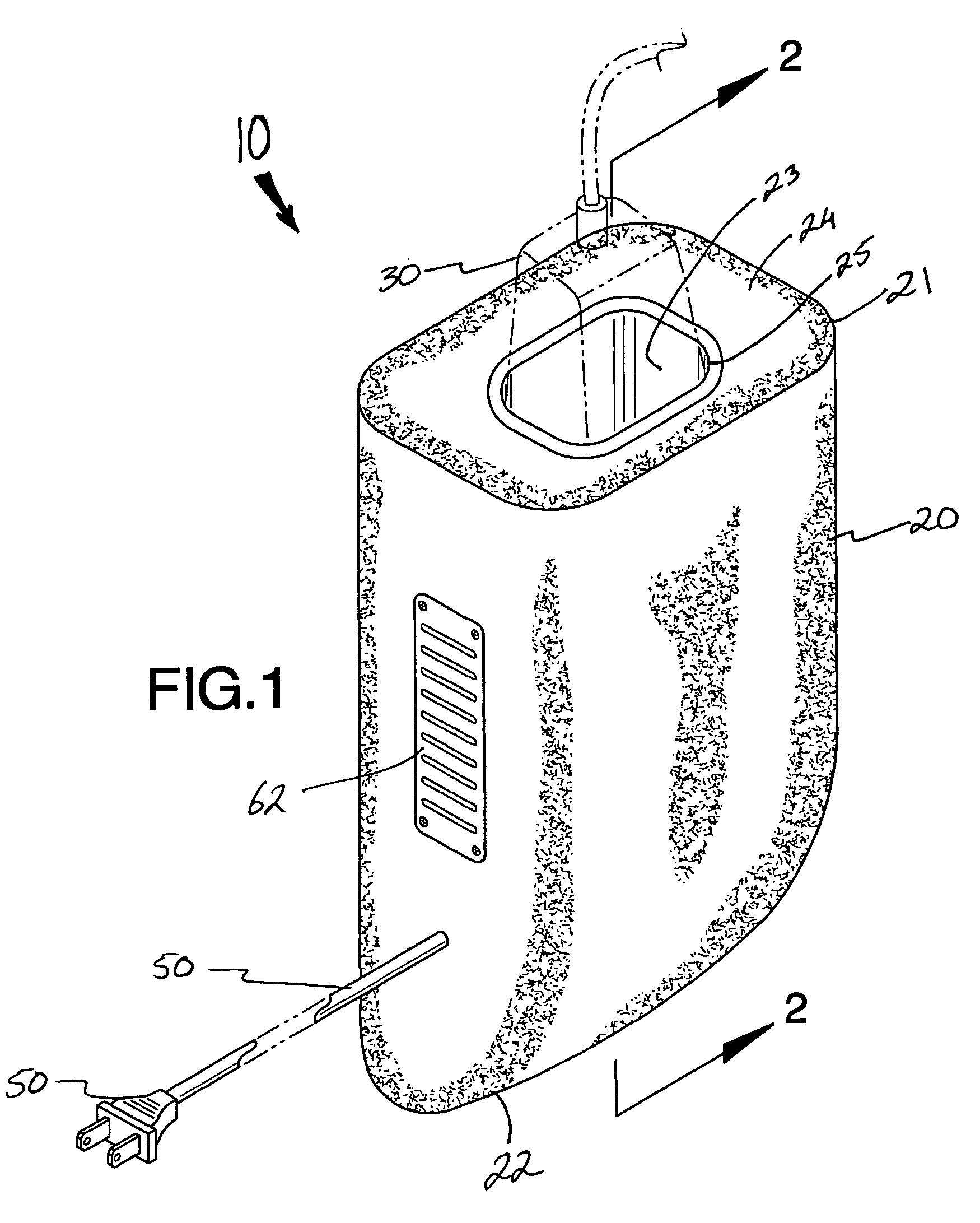
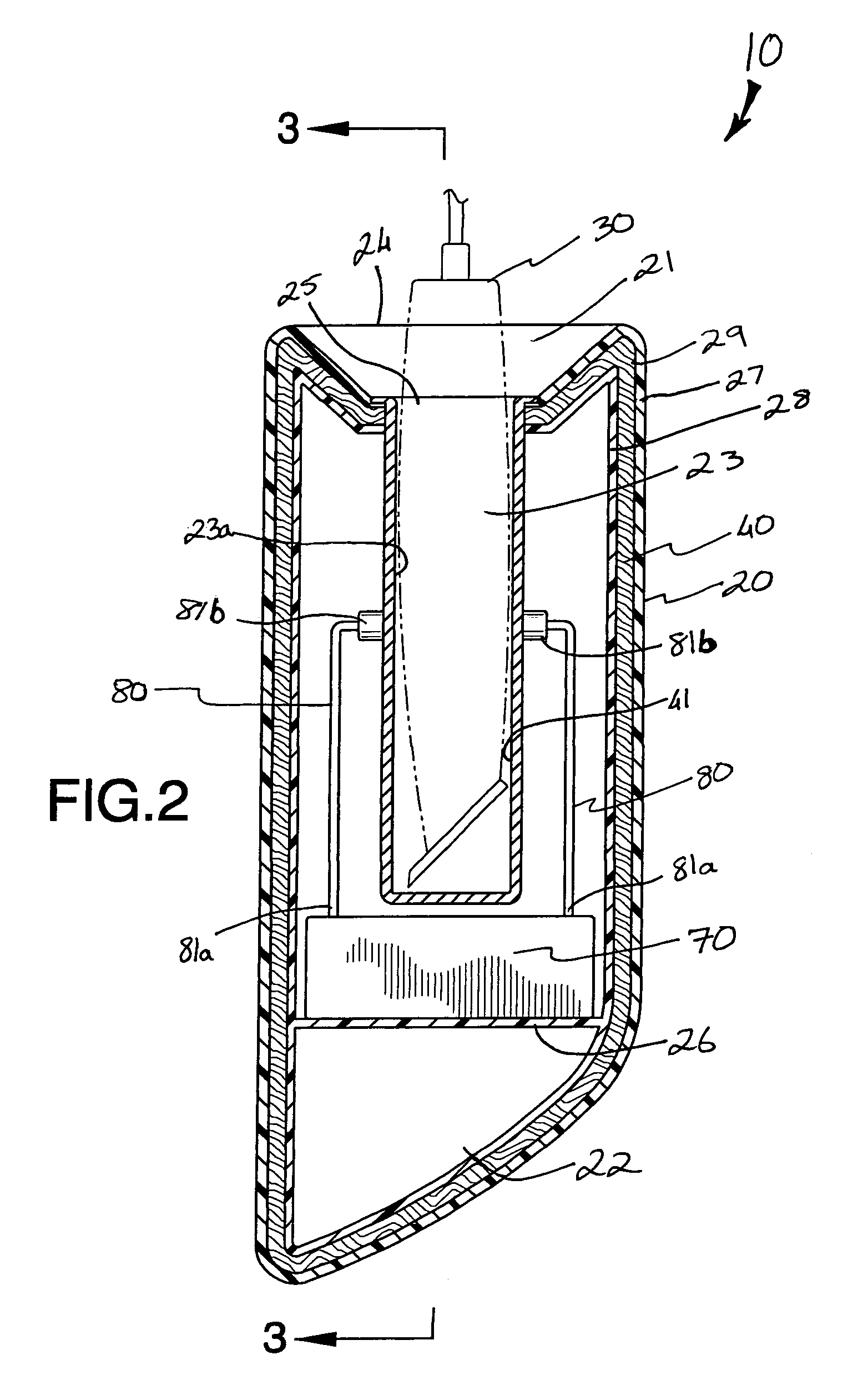
[0023]The device of this invention is referred to generally in FIGS. 1–5 by the reference numeral 10 and is intended to provide a utensil cooling device. It should be understood that the device 10 may be used to cool many different types of heat-generating utensils and should not be limited to only electrical hairstyling clippers.

[0024]Referring initially to FIG. 1, the device 10 includes a body 20 that has top 21 and bottom 22 portions defin...


PUM


Abstract

An electric clipper cooling device includes a body that has a cavity, spaced inner and outer layers, an external power source, a combination fan and vent, and a thermoelectric cooler disposed therein. A heat absorbing material is disposed between said inner and outer layers and lies adjacent the cavity for assisting to draw heated air outwardly therefrom. A plurality of elongated tubes are connected to the cooler and the cavity respectively for allowing the exchange of air therebetween. Air that has a first temperature is drawn to the cooler via one of the tubes and air that has a second temperature is introduced to the cavity via another of the tubes so that an electric device disposed within the body can be cooled during non-operating conditions.

Description

CROSS REFERENCE TO RELATED APPLICATIONS[0001]Not Applicable.STATEMENT REGARDING FEDERALLY SPONSORED RESEARCH OR DEVELOPMENT[0002]Not Applicable.REFERENCE TO A MICROFICHE APPENDIX[0003]Not Applicable.BACKGROUND OF THE INVENTION[0004]1. Technical Field[0005]This invention relates to a cooling device and, more particularly, to a utensil cooling device for electric hairstyling clippers and like devices.[0006]2. Prior Art[0007]The use of electric hair clippers is well known in the industry. Professional hair salons, local barbers, pet groomers and individuals at home all use these devices. A common problem that occurs with devices such as electrical hair clippers is heat generated by the movable blades, due to friction, and heat generated from the electrical current used to power such devices.[0008]This heat can inconveniently be transferred to the hands of the person using the device, resulting in sweating, that can lead to the individual dropping the device. Damage is thus inflicted to...

Claims


Application Information

Patent Timeline
Patent Type & Authority Patents(United States)
IPC IPC(8): F25B21/02
CPCA45D44/00F25B21/02F25B2321/0251F25D17/08
Inventor HENDERSON, ANTHONY C.MOORE, STEVEN B.
Owner HENDERSON ANTHONY C
Why Eureka
Try Eureka