Cooking device with a fan and a water supply

a technology of cooking device and water supply, which is applied in the field of cooking device with a fan and a water supply, can solve the problems of relatively small centrifugal force, relatively lowperipheral speed of the described hub components, and non optimal distribution of water droplets, which remains relatively larg

Inactive Publication Date: 2008-02-05
MKN MASCHFAB KURT NEUBAUER
View PDF21 Cites 77 Cited by
  • Summary
  • Abstract
  • Description
  • Claims
  • Application Information

AI Technical Summary

Problems solved by technology

The disadvantage with all of the aforementioned concepts is that the peripheral speed of the described hub components is naturally relatively very low due to the proportionately small diameter of the hub.
This relatively low peripheral speed leads to a relatively small centrifugal force and thus to a non optimal distribution of the water droplets which remain relatively large.
If one were to increase the rotational speed of the fan i.e. the rotational speed of the fan motor in the fan in order to improve the effectiveness of the arrangement, then this would lead to the need for higher powered motors thereby increasing the costs both for the cooking device and for the operation thereof, this being something that is not desired.
In addition, the higher air speeds then ensuing in the cooking area are neither necessary nor desirable.
The disadvantage of these constructions is the relatively high expenditure and the complexity of the final installation.
This leads to high costs and, in particular, makes cleaning of the corresponding cooking devices substantially more difficult.
In addition, the uniformity of the distribution process and thus the efficiency of the arrangements are unsatisfactory.

Method used


Image

  • Cooking device with a fan and a water supply
  • Cooking device with a fan and a water supply

Examples


Embodiment Construction

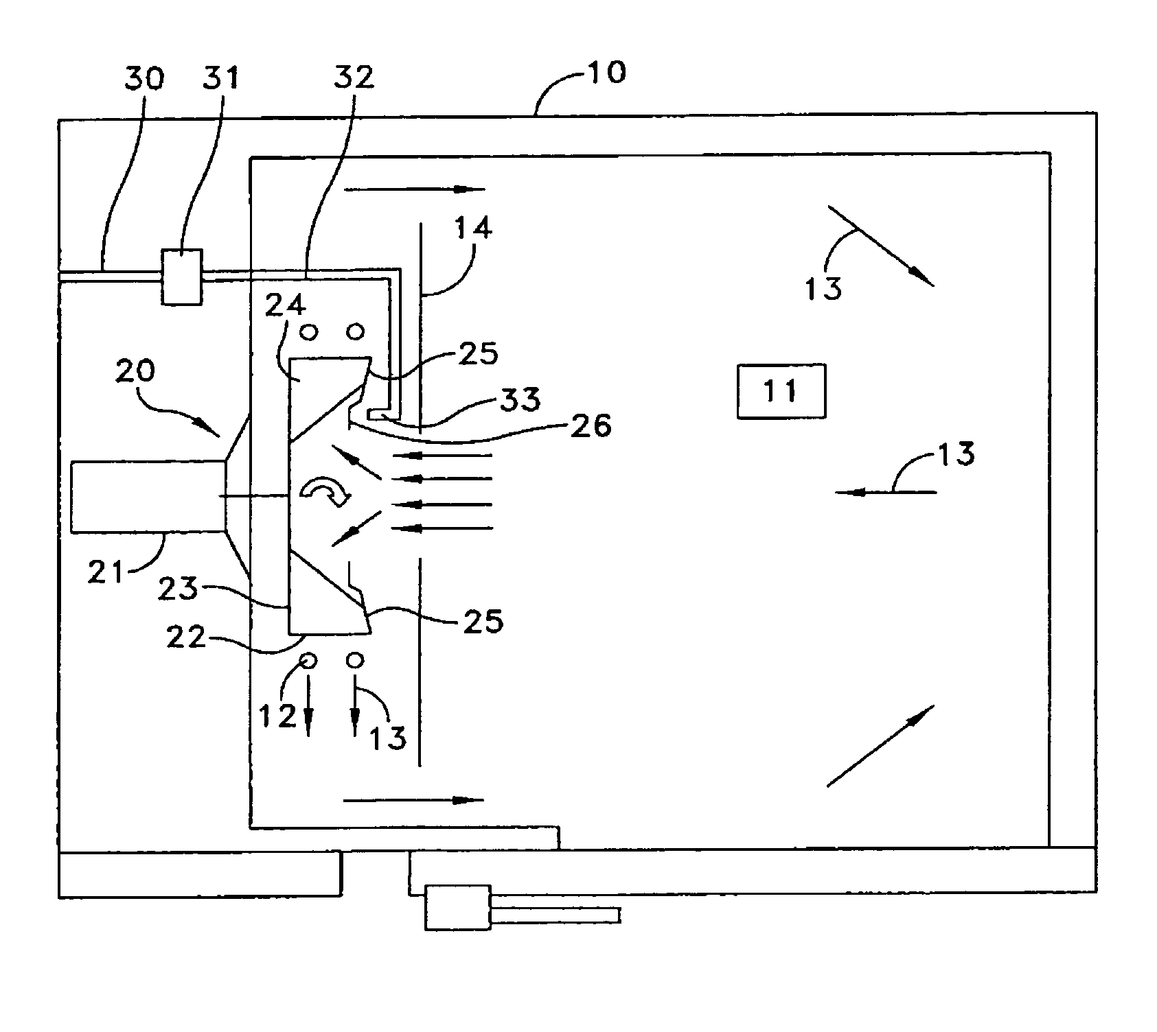
[0030]A cooking device, for example a combination steamer, a baking-oven or other type of hot-air device is schematically illustrated in FIG. 1 in the form of a sectional view as seen by the user. This cooking device 10 includes a cooking area 11. A heating element 12 is provided in the cooking area 11 at the left-hand side although only two schematically-indicated turns thereof can be perceived. The heating of the cooking area 11 can be effected either by means of electrical heating elements 12 or else by means of heating elements 12 in the form of heat exchanger pipes through which a hot medium flows. Other types of device for producing heat could also be employed as heating elements 12.

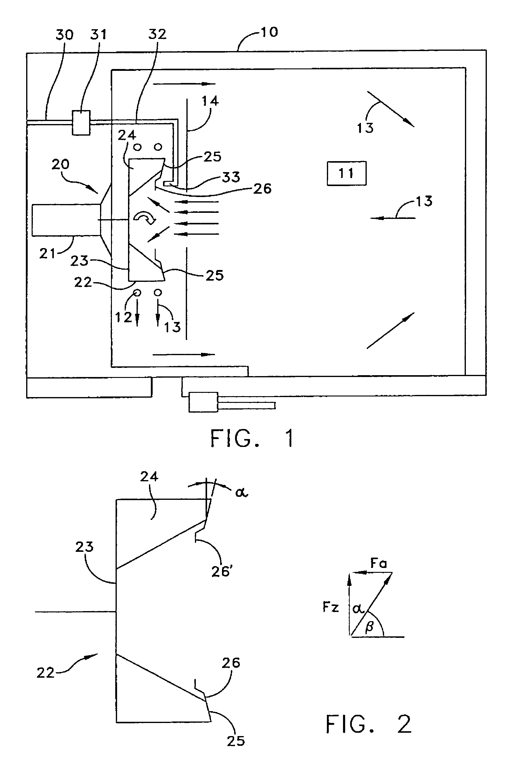
[0031]A fan 20 is provided in order to uniformly distribute the heat produced by the heating element 12 or the air that has been heated thereby throughout the cooking area 11. This fan 20 includes a fan motor 21 which drives a radial flow impeller 22 in the cooking area 11. The radial flow impeller...


PUM


Abstract

A cooking device comprises a cooking chamber (11) and one or more heating elements (12). Furthermore, a blower (20) is provided, which comprises a radial blower impeller (22) and an atomisation element rotating with the radial blower impeller (22). A water supply (30) comprises at least one water outlet (33), which supplies water onto the atomisation element (25). An evaporation of the water and thus a humid cooking chamber air is achieved. The atomising element is a discoidal, axially-symmetrical element, the outer radius of which is the same as, or larger than the inner radius of the blade region of the radial blower impeller (22). The atomisation element is arranged adjacent to the radial blower impeller in the axial direction and the water outlet (33) is arranged adjacent to the atomisation element (25), outside the radial blower impeller (22).

Description

TECHNICAL FIELD[0001]The invention relates to a cooking device comprising a cooking area, one or more heating elements, a fan incorporating a radial flow impeller having a blade region, a disk-shaped axially-symmetrical atomization element which rotates with the radial flow impeller, and a water supply having at least one water outlet which delivers water to the atomization element.BACKGROUND[0002]Cooking devices are being equipped to an increasing extent with a steam generating system for improving the results of the cooking process with the help of the damp air which then ensues in the cooking area. Such cooking devices are, for example, combination steamers, baking-ovens or hot-air ovens. They serve, in particular, for the purposes of preparing food for consumption. On the one hand hereby, it is possible to produce steam by means of a steam generator located externally of the cooking area and then feed this steam into the cooking area through a connecting member.[0003]However, in...

Claims


Application Information

Patent Timeline
Patent Type & Authority Patents(United States)
IPC IPC(8): A23L1/00F24C15/32
CPCF24C15/327
Inventor HELM, PETER
Owner MKN MASCHFAB KURT NEUBAUER
Why Eureka
Try Eureka