
Loudspeaker with progressively damped acoustical chamber

Inactive Publication Date: 2008-02-05
BUDGE TIERRY R
View PDF6 Cites 12 Cited by
  • Summary
  • Abstract
  • Description
  • Claims
  • Application Information

AI Technical Summary

Benefits of technology

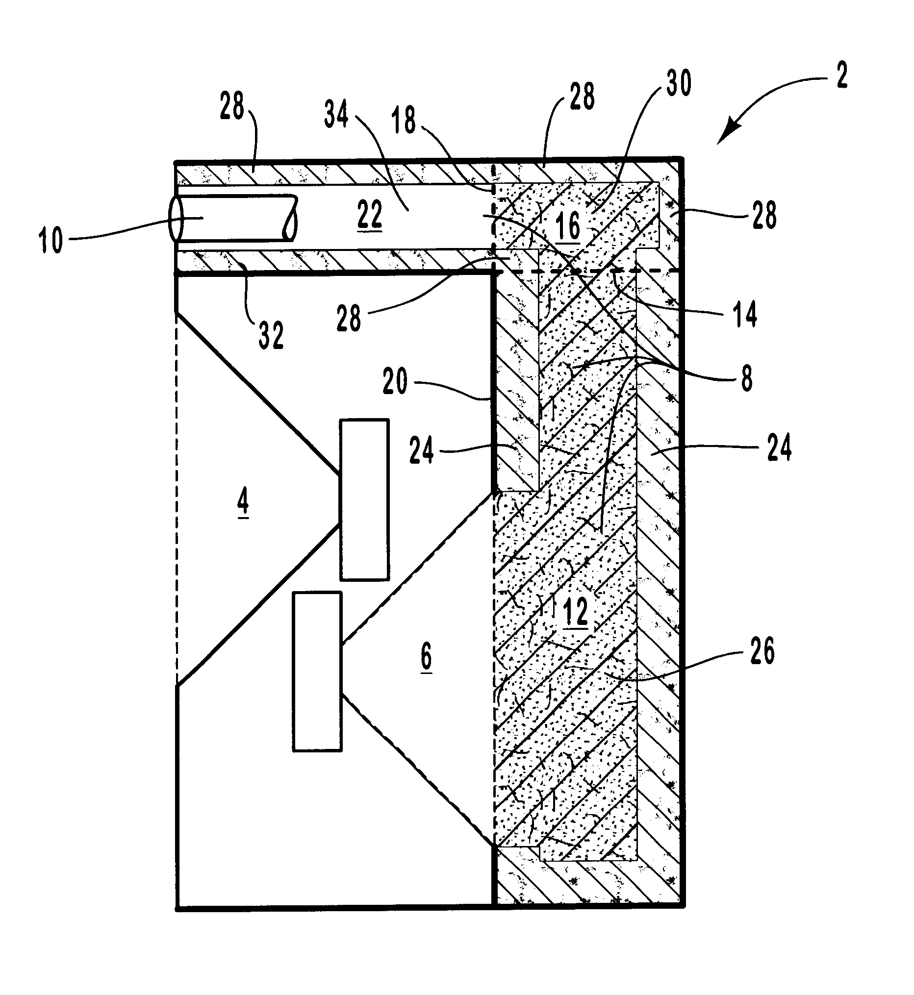
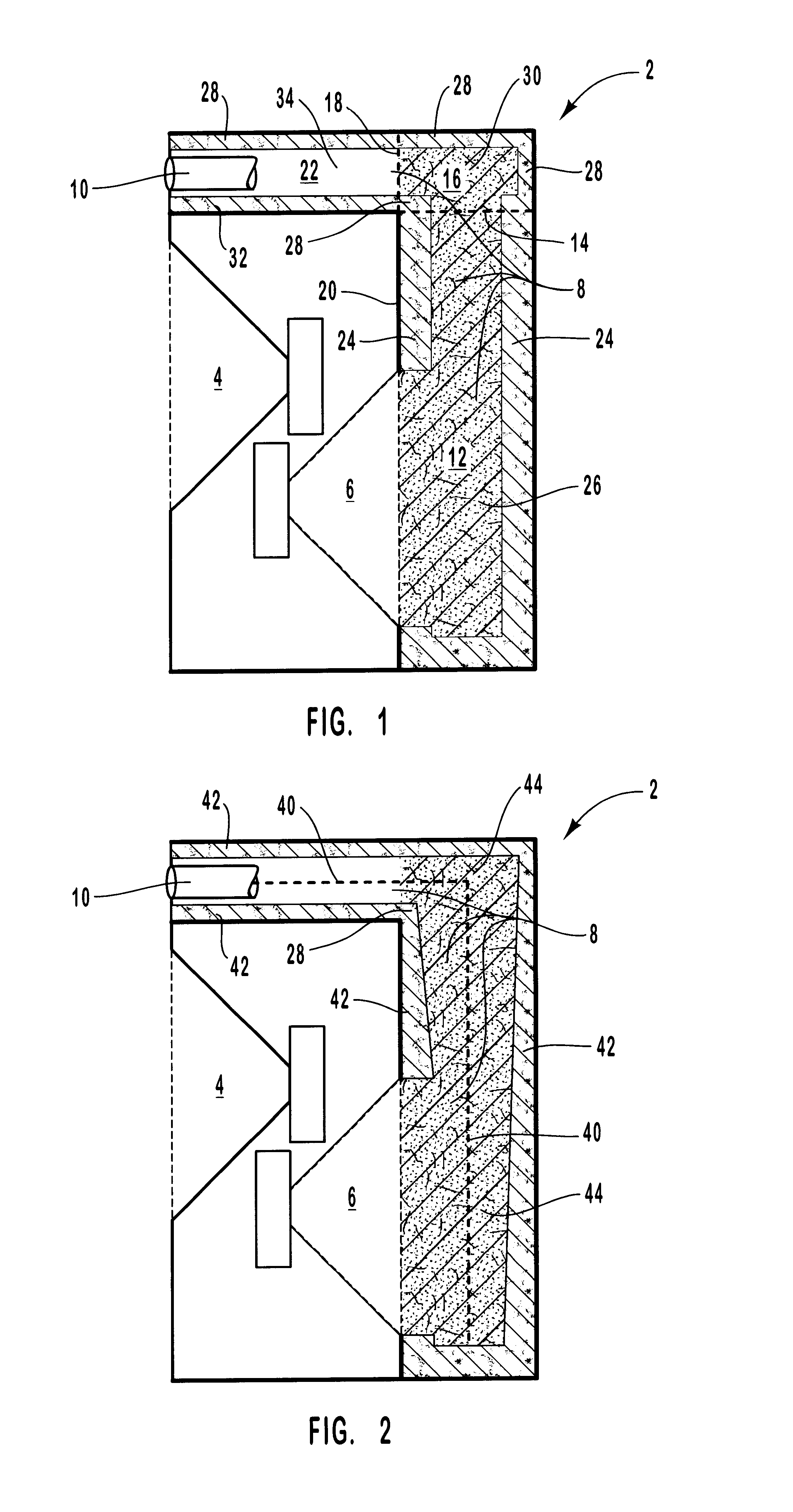
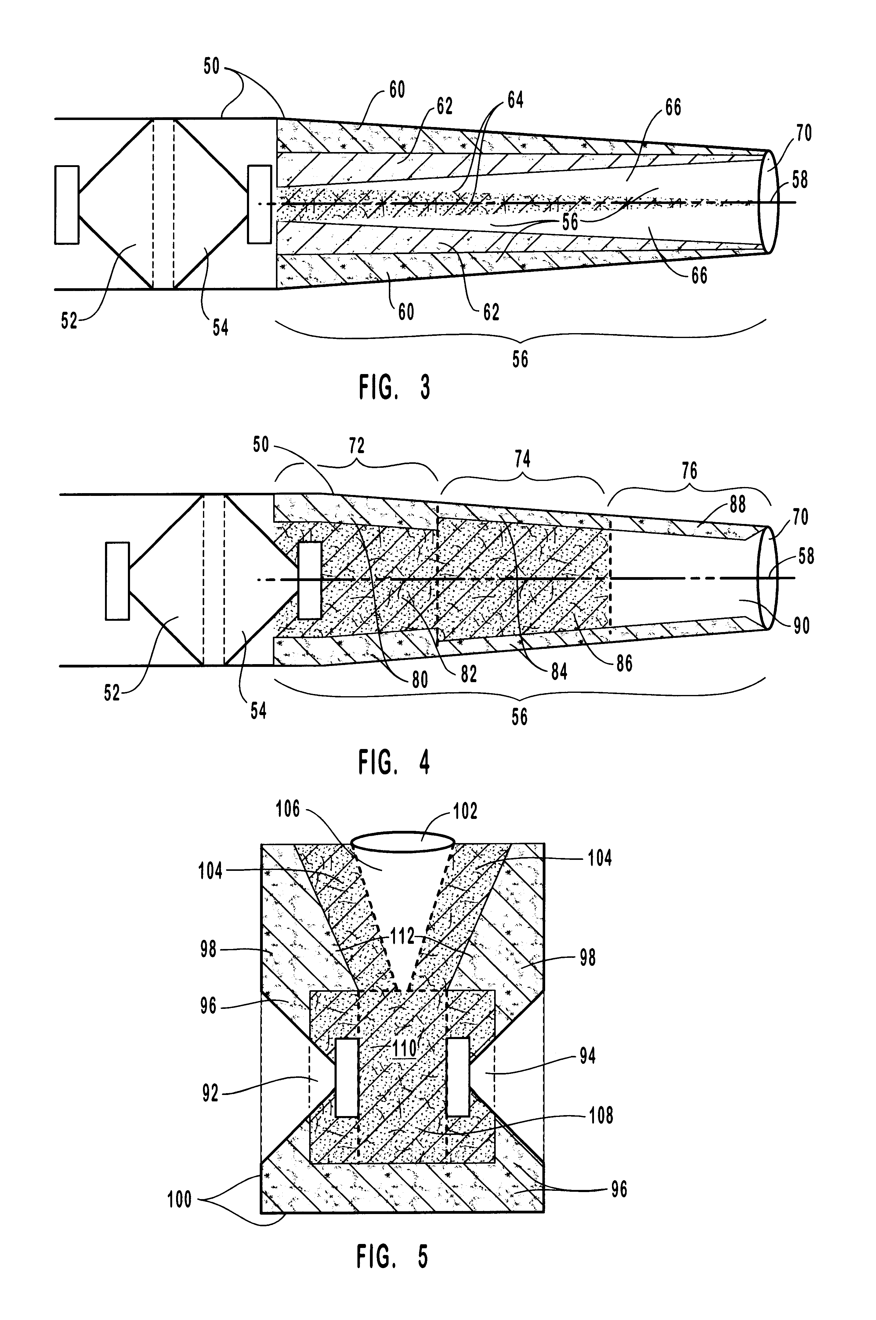
[0014]The damping structure of preferred embodiments of the present invention decreases in density as its distance from a driver increases. This decrease in density creates a decrease in resistance experienced by a sound wave which helps direct the sound wave to a destination and help prevent sound waves from following an opposite path. The effect is much like a pressurized fluid following a path of least resistance. The damping material is placed in a manner that will promote movement of sound waves from the driver through the chamber and toward the exterior of the enclosure.
[0017]Accordingly, it is an object of some embodiments of the present invention to provide a loudspeaker with improved sound reproduction.
[0018]It is another object of some embodiments of the present invention to provide a loudspeaker with reduced cancellation.
[0019]It is yet another object of some embodiments of the present invention to provide a loudspeaker with reduced interference.

Problems solved by technology

One problem inherent in typical driver design is the “backwave” created when the diaphragm rebounds from an extended position.
This creates a sound wave which emanates from the back of the diaphragm which, if not controlled, may interfere with and even cancel the primary sound wave created by the diaphragm.
All of these methods help somewhat to eliminate backwave interference, however they do so at the cost of lost energy and performance.
This eliminates the backwave cancellation problem because the waves are in-phase, but the drivers can suffer from a decreased response and lost energy due to the need to overcome increased pressure in the enclosure.
Another problem inherent with woofers which must move fair distances in order to reproduce low frequencies and large outputs is that of inertia.
Inertia makes stopping a diaphragm at a neutral position difficult after a substantial displacement.
However, even if a driver is designed to near mechanical perfection, with the restorative force being equal to that of the initial current, stopping the driver at the “neutral” position remains a challenge.
An additional problem with current speaker technology is caused by misalignment of the voice coil with the permanent magnet due to distortion of the diaphragm or cone.
Driver surrounds and spiders must be flexible to provide the necessary response to electrical input, but this makes the driver diaphragm extremely susceptible to unequal air pressure across its surface area.
This causes the precisely balanced magnetic fields of the permanent magnet and the voice coil to misalign thereby causing an inductive variance and increased current draw from the amplifier.
This results in decreased power handling, poorer response and inaccurate reproduction of sound.
Backwave and air pressure problems are complicated by the fact that while a build-up of pressure is deleterious to linear operation, a certain amount of back pressure can help control driver inertial problems.

Method used


Image

  • Loudspeaker with progressively damped acoustical chamber
  • Loudspeaker with progressively damped acoustical chamber
  • Loudspeaker with progressively damped acoustical chamber

Examples


Embodiment Construction

[0026]In the following description, preferred embodiments of the present invention are described by referring to functional diagrams, schematic diagrams, functional flow charts, program flow charts and other graphic depictions which help to illustrate either the structure or processing of preferred embodiments used to implement the apparatus, system and method of the present invention. Using the diagrams and other depictions in this manner to present the invention should not be construed as limiting of its scope.

[0027]In reference to FIG. 1, a first embodiment of the present invention comprises a speaker enclosure 2 with an exterior driver 4 and an interior driver 6 mounted therein. An acoustical chamber 8 is formed in enclosure 2. Chamber 8 extends from driver 6 to the exterior of the enclosure and may terminate at the exterior in a port 10 or some other type of opening. Chamber 8, as shown in this embodiment, may be regarded as having three sections. A first section 12 begins near...


PUM


Abstract

The present invention relates to a novel acoustical chamber for enclosed loudspeakers which help direct and control sound waves within the enclosure thereby enhancing sound output. The present invention utilizes a method of progressive damping which utilizes multiple layers of damping material or layers of material with variable density or damping characteristics within an enclosed chamber. The damping material is arranged such that the density of the material in the chamber decreases as the distance from the driver increases. The damping materials may also be configured such that the density of the material in the chamber increases as the transverse distance from the center of the chamber increases, that is, the density of the material along the outer surfaces of the chamber is denser than material which is transversely inward from the outer surfaces.

Description

THE FIELD OF THE INVENTION[0001]The present invention relates to the field of high-quality audio loudspeakers and more particularly to enclosed loudspeakers with ported or sealed acoustical chambers for manipulation of driver backwaves. The speakers of the present invention comprise one or more acoustical chambers with multiple layers of damping materials which become less dense as the distance from the driver increases. Additionally, the acoustical chambers of preferred embodiments of the present invention decrease in cross sectional area, to a minimum cross-sectional area equal to that of the driver's surface area, and narrow to this “minimum” at the greatest distance from a driver.BACKGROUND[0002]Loudspeakers are essentially transducers which convert electrical energy into physical, acoustical energy. The design of typical basic loudspeakers has not changed for decades. Generally, a loudspeaker driver consists of a frame or housing, a cone or other diaphragm attached to a voice c...

Claims


Application Information

Patent Timeline
IPC IPC(8): H05K5/00H04R1/28
CPCH04R1/288H04R1/2888
Inventor BUDGE, TIERRY R.
Owner BUDGE TIERRY R
Learn More