Constant edge-rate ternary output consecutive-edge modulator (CEM) method and apparatus

a consecutive edge modulator and constant edge rate technology, applied in the field of consecutive edge modulators, can solve the problems of low attenuation of artifacts introduced by alternation, distortion and non-linearity, and simple alternation is generally undesirabl

Active Publication Date: 2008-02-05
CIRRUS LOGIC INC
View PDF19 Cites 7 Cited by
  • Summary
  • Abstract
  • Description
  • Claims
  • Application Information

AI Technical Summary

Benefits of technology

[0014]Optionally, all possible codes from the noise shaper could be permitted through the code splitter, so that infrequent occurrences of periods with no pulse can be permitted. Alternatively, the pulse edges prior to and following a given pulse edge can be observed and if both have a width less than the entire pulse portion edge position range on both outputs, then a code that will generate no transition on either output can be permitted for the given pulse portion.

Problems solved by technology

Simple alternation is generally undesirable, since the attenuation of artifacts introduced by the alternation is low unless the oversampling rate is very high.
Permitting the range of edge positions to extend to represent either type of non-transitioning code results in distortion and non-linearity in the result of the CEM conversion, when sequentially adjacent samples on one or more of the outputs are at the maximum or minimum value.
However, such a solution causes loss of substantial dynamic range where the number of overall codes is small.
All other values can be supported by the two outputs without having one of the outputs in the off condition for any sample interval, but as noted above, the penalty is loss of substantial potential dynamic range.

Method used


Image

  • Constant edge-rate ternary output consecutive-edge modulator (CEM) method and apparatus
  • Constant edge-rate ternary output consecutive-edge modulator (CEM) method and apparatus
  • Constant edge-rate ternary output consecutive-edge modulator (CEM) method and apparatus

Examples


Embodiment Construction

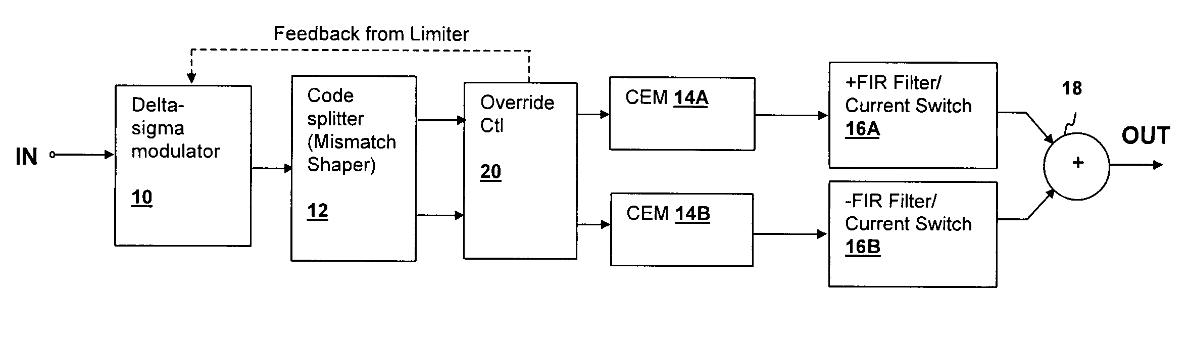
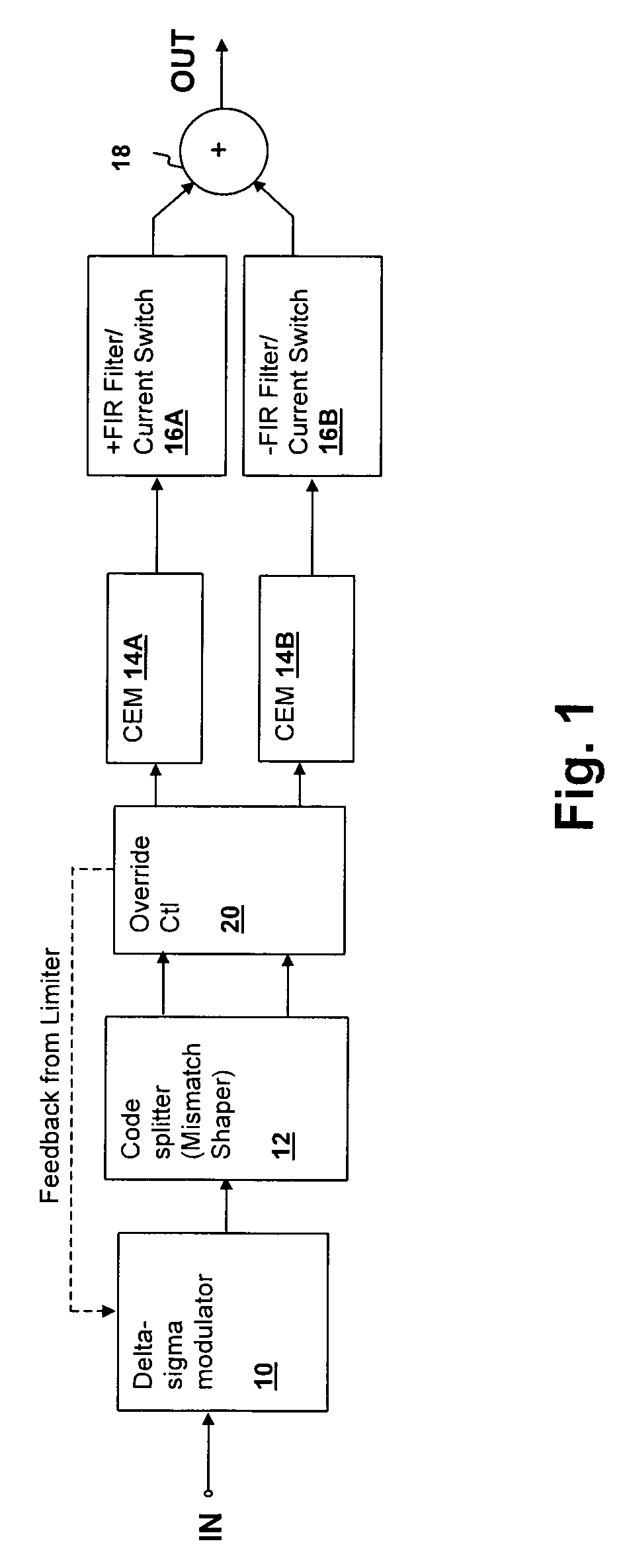
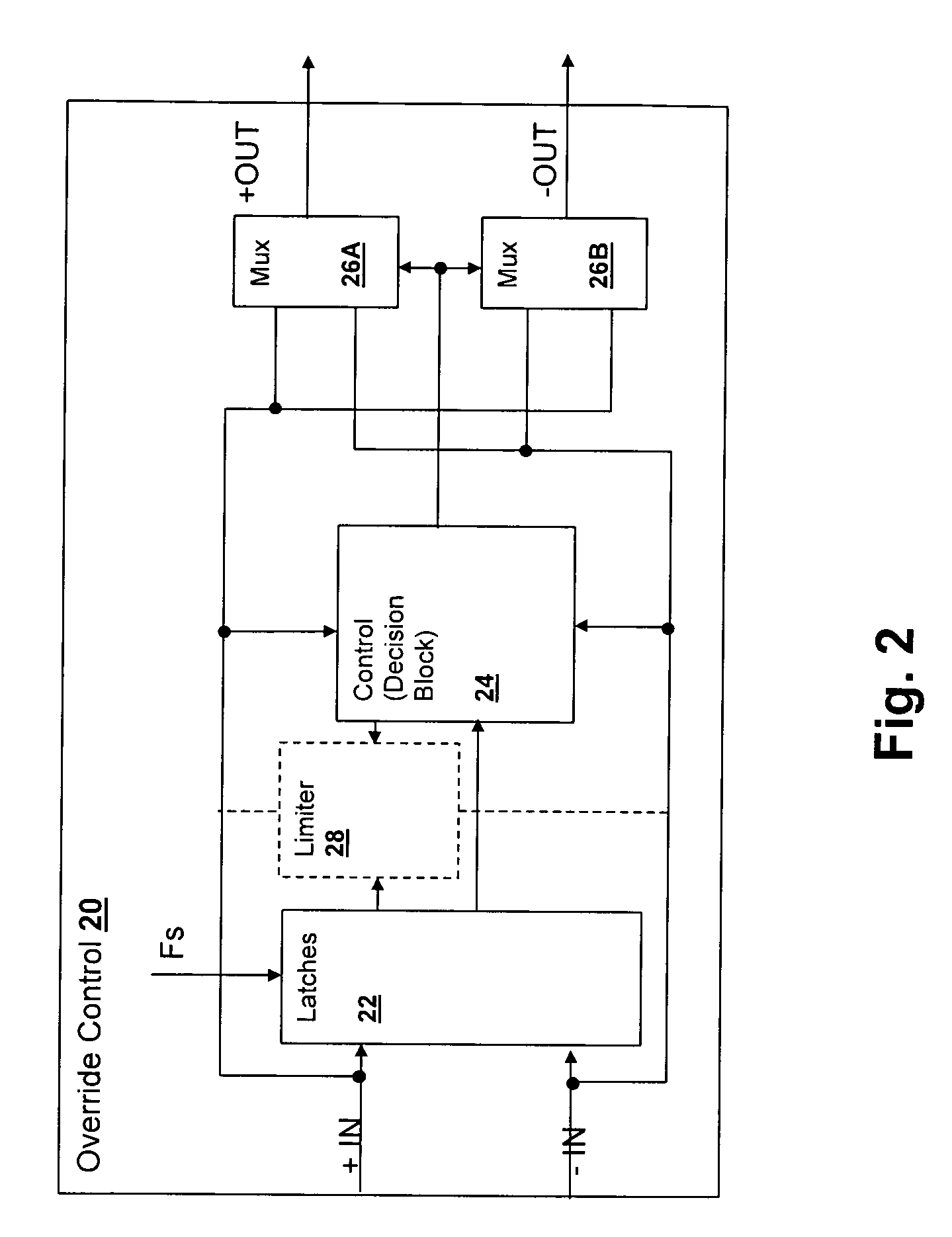
[0021]The present invention encompasses a method and apparatus for producing a ternary consecutive edge modulated signal having an extended dynamic range, while maintaining a constant edge rate. The dynamic range is extended without distortion or with reduced distortion by violating the code splitter's ordinary assignment of the remainder count portion of CEM codes (the extra count in odd counts) in a dual-stream CEM that implements a ternary CEM. The remainder count assignment is generally made by a mismatch shaper that takes the output of the quantizer of a delta-sigma modulator noise-shaper and assigns codes between two pulse outputs provided by corresponding CEMs according to the mismatch shaper's response and the code history. However, other remainder count assignment mechanisms may be used to assign the remainder counts and the present invention extends to any multi-stream CEM in which codes are reassigned between the streams to avoid sequentially adjacent maximum or minimum c...


PUM


Abstract

A constant edge-rate ternary output consecutive-edge modulator (CEM) method and apparatus provides improved dynamic range in a noise-shaped CEM ternary pulse generator. A noise shaper shapes an input signal that is supplied to a pair of CEMs through a mismatch shaper or other code splitter that assigns unequal pulse width portions (the extra count in odd counts) between the pair of CEMs. The range of pulse width out of the CEMs can then be allowed to extend to the full sample period for one or possibly both of the CEMs in a given cycle. A control circuit overrides the mismatch shaper's assignment of the unequal pulse width portions when a previous pulse period yielded no transition from a given CEM, so that the given CEM is guaranteed to have a transition in the current pulse period.

Description

CROSS-REFERENCE TO RELATED APPLICATIONS[0001]This application claims priority under 35 U.S.C. §119(e) to U.S. Provisional Patent Application Ser. No. 60 / 729,685, filed on Oct. 24, 2005. This application is further related to co-pending application Ser. No. 11 / 297,011, filed on Dec. 8, 2005 and entitled “EXTENDED DYNAMIC RANGE CONSECUTIVE EDGE MODULATION (CEM) METHOD AND APPARATUS”. The above-referenced application and the present application have at least one inventor in common and are assigned to the same Assignee.BACKGROUND OF THE INVENTION[0002]1. Field of the Invention[0003]The present invention relates generally to consecutive edge modulators, and more specifically, to a consecutive-edge modulator (CEM) having a ternary output and a constant edge-rate.[0004]2. Background of the Invention[0005]Consecutive edge modulators (CEMs) are desirable in applications such as digital-to-analog (D / A) converters and power output circuits due to the effectively doubled control update rate at ...

Claims


Application Information

Patent Timeline
Patent Type & Authority Patents(United States)
IPC IPC(8): H03M3/00
CPCH03K7/08H03M1/822G06F1/025H03M3/506
Inventor TROTTER, BRIAN DAVIDMELANSON, JOHN L.
Owner CIRRUS LOGIC INC
Why Eureka
Try Eureka