Data transmission device and data transmission method

a data transmission device and data transmission technology, applied in data switching networks, instruments, baseband system details, etc., can solve the problem that the conventional data transmission device cannot reduce and achieve the effect of reducing the total current flowing through the signal lin

Active Publication Date: 2008-02-05
RENESAS ELECTRONICS CORP
View PDF12 Cites 4 Cited by
  • Summary
  • Abstract
  • Description
  • Claims
  • Application Information

AI Technical Summary

Benefits of technology

[0019]Therefore, the outputs of the parallel data control unit enables the frequency of occurrence of a bit representing the second logic level to be higher than the frequency of occurrence of a bit representing a first logic level and enables a reduction in the total current flowing through the signal lines.
[0020]According to the above invention, the total current flowing through the signal lines can be effectively reduced.
[0022]According to the above invention, the total current flowing through the signal lines can be effectively reduced.
[0025]Therefore, the output of the parallel data control unit enables the frequency of occurrence of the bit representing the second logic level to be higher than the frequency of occurrence of the bit representing the first logic level, whereby the total current flowing through the signal lines can be reduced.

Problems solved by technology

The problem of the large total current flowing through the signal lines is not limited to LCD modules handling parallel data.
It has now been discovered that, conventional data transmission device is unable to decrease total current flowing through the signal lines.

Method used


Image

  • Data transmission device and data transmission method
  • Data transmission device and data transmission method
  • Data transmission device and data transmission method

Examples


first embodiment

[0037]A first embodiment of the present invention will be described hereinbelow with reference to the drawings.

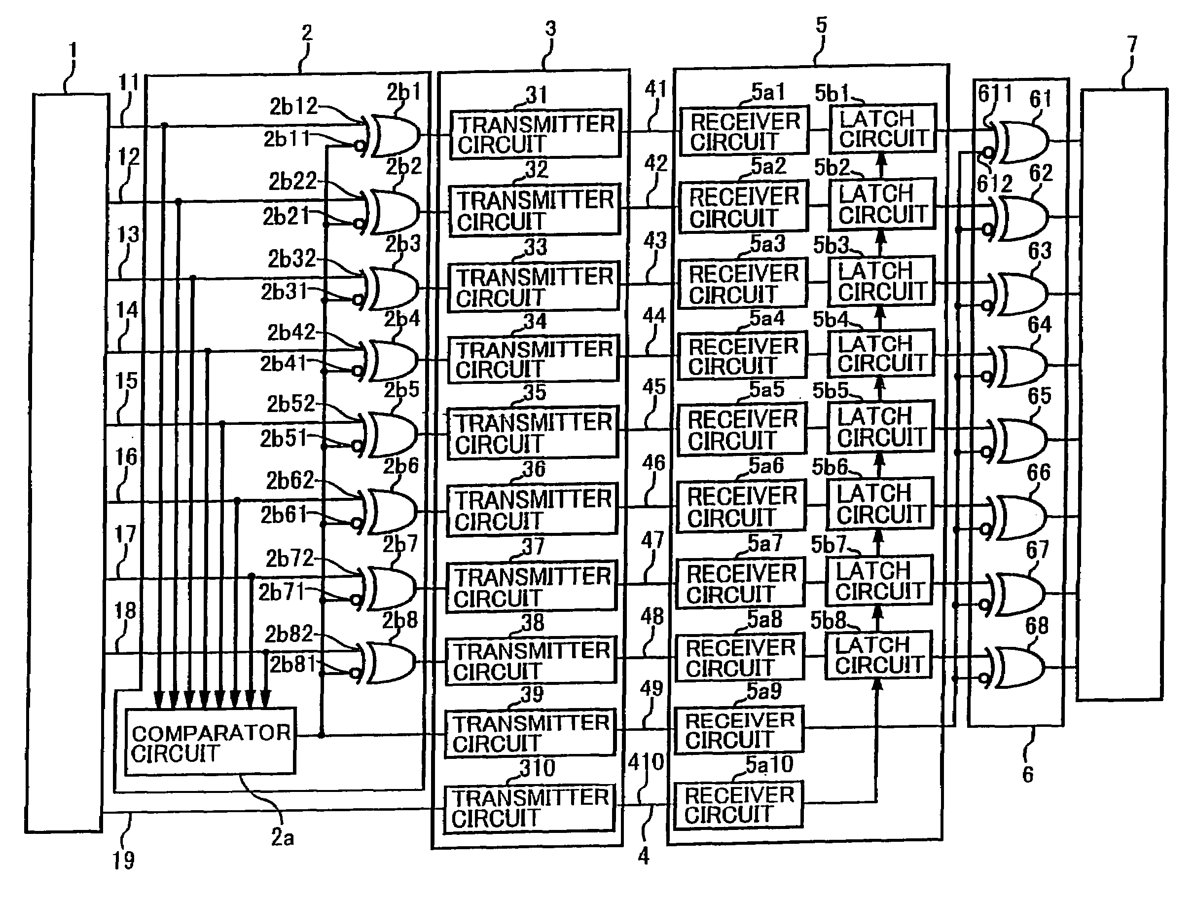
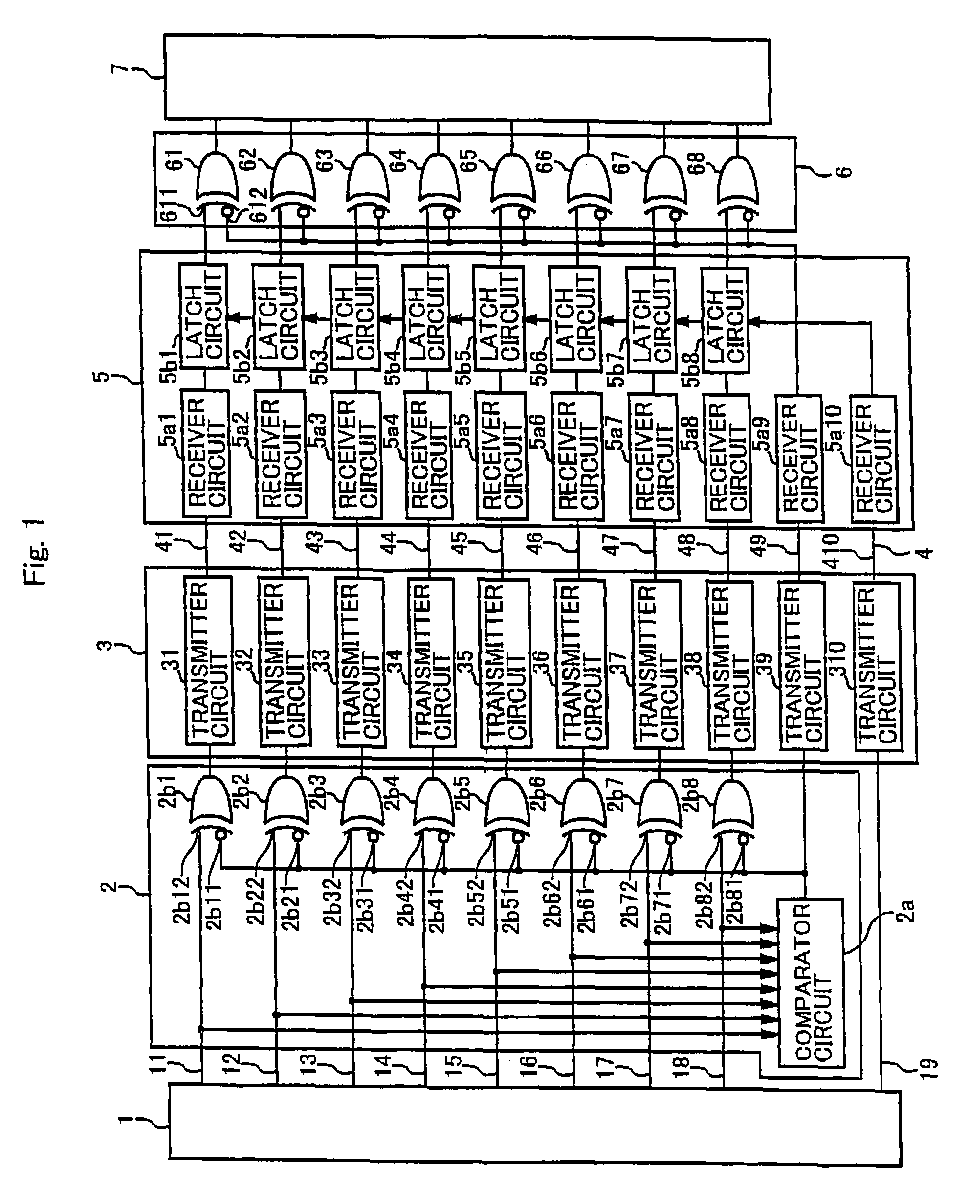
[0038]FIG. 1 is a block diagram showing a data transmission device of an embodiment of the present invention.

[0039]In FIG. 1, the data transmission device of the present invention comprises a transmission-side LSI 1 constituting the transmission side, a parallel data control unit 2, a data transmitter portion 3, a plurality of signal lines 4m (more specifically, signal lines 41 to 49 and a signal line 410), a data receiver portion 5, a parallel data supply control unit 6 and a reception-side LSI 7 constituting the reception side.

[0040]The transmission-side LSI 1 outputs parallel data of a plurality of bits. In this embodiment, the transmission side LSI 1 uses 8-bit parallel data as parallel data of a plurality of bits. Further, the plural-bit parallel data is not limited to 8-bit parallel data and can be suitably varied as long as the parallel data has a plurality of bits. ...

second embodiment

[0122]A data transmission device of a second embodiment is explained hereinbelow. This data transmission device is used for a driver IC of a LCD panel. As shown in FIG. 7, a plurality of driver ICs 201 are mounted on a LCD panel 200. A transmission line 202 is formed on the LCD panel 200, where the plurality of driver ICs 202 are connected in cascade. Each of the driver ICs 201 includes a transmitter portion and a receiver portion of the data transmission device of this invention. Data is transmitted and received between adjacent driver ICs 201. Specifically, the data transmitted from a transmitter portion of one driver IC 201 is received by a receiver portion of an adjacent driver IC 201. In this way, data is sequentially transmitted through the transmission line 202 from an upstream driver IC 201 to a downstream driver IC 201.

[0123]FIG. 8 is a circuit diagram showing the structure of two adjacent driver ICs 201 mounted on the LCD panel 200 shown in FIG. 7. The structure of the dat...


PUM

PropertyMeasurementUnit
currentaaaaaaaaaa
resistance valueaaaaaaaaaa
transmissionaaaaaaaaaa

Abstract

The data transmission device transmits parallel data of a plurality of bits. The data transmission device includes a parallel data control unit that outputs parallel data for which the logic level of each bit of the parallel data is inverted when the number of bits representing a first logic level is greater than the number of bits representing a second logic level, a data transmitter portion that allows a second current that is larger than a first current representing the first logic level to flow to signal lines corresponding with a bit representing the second logic level; and a parallel data supply control unit that supplies parallel data for which the logic level of each bit of the parallel data is inverted to the reception side.

Description

BACKGROUND OF THE INVENTION[0001]1. Field of the Invention[0002]The present invention relates to a data transmission device and a data transmission method and, more particularly, to a data transmission device and a data transmission method that transmit parallel data.[0003]2. Description of Related Art[0004]Data transmission devices transmit parallel data from a transmission side to a reception side.[0005]For example, in a liquid crystal display device (hereinafter as ‘LCD module’), 6-bit or 8-bit parallel data is used as data for each of red (R), green (G) and blue (B) colors. The parallel data for each color is transmitted from a control LSI at the transmission side to a driver LSI at the reception side.[0006]More specifically, the control LSI transmits data from a built-in transmitter (Tx) to parallel signal lines and the reception-side driver LSI receives data from the parallel signal lines by means of a built-in receiver (Rx). In the case of small size LCD modules, a controller...

Claims


Application Information

Patent Timeline
Patent Type & Authority Patents(United States)
IPC IPC(8): G09G5/00G09G3/36G02F1/133G06F13/38G06F15/00G09G3/20H04L12/00H04L17/02H04L25/02
CPCG09G3/2092G09G3/3685G09G5/006G09G2352/00G02F1/133G09G3/36H04L12/00H04L17/02
Inventor YUSA, KAZUYUKI
Owner RENESAS ELECTRONICS CORP
Why Eureka
Try Eureka