Register inlet apparatus for a central vacuum cleaning system

a vacuum cleaning and register technology, applied in the field can solve the problems of poor indoor air quality, dry eyes, nasal congestion, etc., and achieve the effects of reducing the modification of the structure of the residence, simplifying the installation of central vacuum cleaning systems, and reducing the cost of professional installation

Inactive Publication Date: 2008-02-12
JENKINS BRADLEY E
View PDF17 Cites 45 Cited by
  • Summary
  • Abstract
  • Description
  • Claims
  • Application Information

AI Technical Summary

Benefits of technology

[0009]In its basic concept this invention provides an inlet for a central vacuum cleaning system that will be simple enough for a novice or do-it-yourself consumer to install a system without the high cost of professional installation or the degree of modification required to the residence for current system installations. This invention will leverage the existing air ducts, also called register boots, used in heating and air conditioning, or HVAC, systems by coupling the traditional register with an inlet for the central vacuum cleaning system. By doing so, modifications to the structure of the residence are minimized as pipe ductwork for the central vacuum cleaning system can be fed through the register boot in the floor. This invention therefore has simplified the installation of central vacuum cleaning systems through the convenient and easy replacement of the traditional register for this new invention. It will no longer be necessary for the pipe ductwork to be installed within walls or floors in order to reach the traditional inlets, thereby eliminating any modifications to walls, baseboards, or floors as previously required by traditional central vacuum cleaning installations. In addition, by minimizing the modifications required to the residence, this invention contributes to enabling the central vacuum cleaning system to be moved from one residence to another, thereby allowing consumers to keep their investment in such systems as they relocate.
[0010]Accordingly, an object of this invention is to provide an inlet that is easy to install in either existing or new construction, residential or commercial.
[0011]Another object of this invention is to provide an inlet that will contribute to the installation of a central vacuum cleaning system with less modification to the residential or commercial structure.
[0012]Another object of this invention is to provide an inlet that will contribute to the ability to move a central vacuum cleaning system from one residential or commercial structure to another.

Problems solved by technology

According to the American Lung Association, poor indoor air quality can cause or contribute to lung disease, including respiratory tract infections, asthma, and lung cancer.
In addition, poor indoor air quality can cause headaches, dry eyes, nasal congestion, nausea and fatigue.
Unfortunately, high efficiency filters such as HEPA and ULPA do not adequately solve the problem of poor air quality in the home.
In addition, during the filter replacement or cleaning process, the consumer is directly exposed to the pollutants.
However, the price and complexity of installation make such systems difficult for the majority of consumers to obtain.
In most cases, professional installation is required due to the complexity of installing the pipe ductwork through the walls and floors of an existing home.
This adds significant cost to the system, making them accessible primarily to the upper end housing industry.
While this decreases the system installation cost for the buyer of a new construction home, it does not solve the problems faced by consumers in existing homes or less costly new homes who must still pay the high installation charges to have their home retrofitted for a system.
The consumer would not be able to relocate the numerous inlets and extensive pipe ductwork that have been permanently installed throughout the walls and floors.
Current inlets for central vacuum cleaning systems do not adequately attempt to simplify or decrease the cost of system installations.
Consequently, a skilled professional must be used to retrofit an existing home for a central vacuum cleaning system due to the complexity of running pipe ductwork through floors and walls to be connected to these inlets.

Method used


Image

  • Register inlet apparatus for a central vacuum cleaning system
  • Register inlet apparatus for a central vacuum cleaning system
  • Register inlet apparatus for a central vacuum cleaning system

Examples


Embodiment Construction

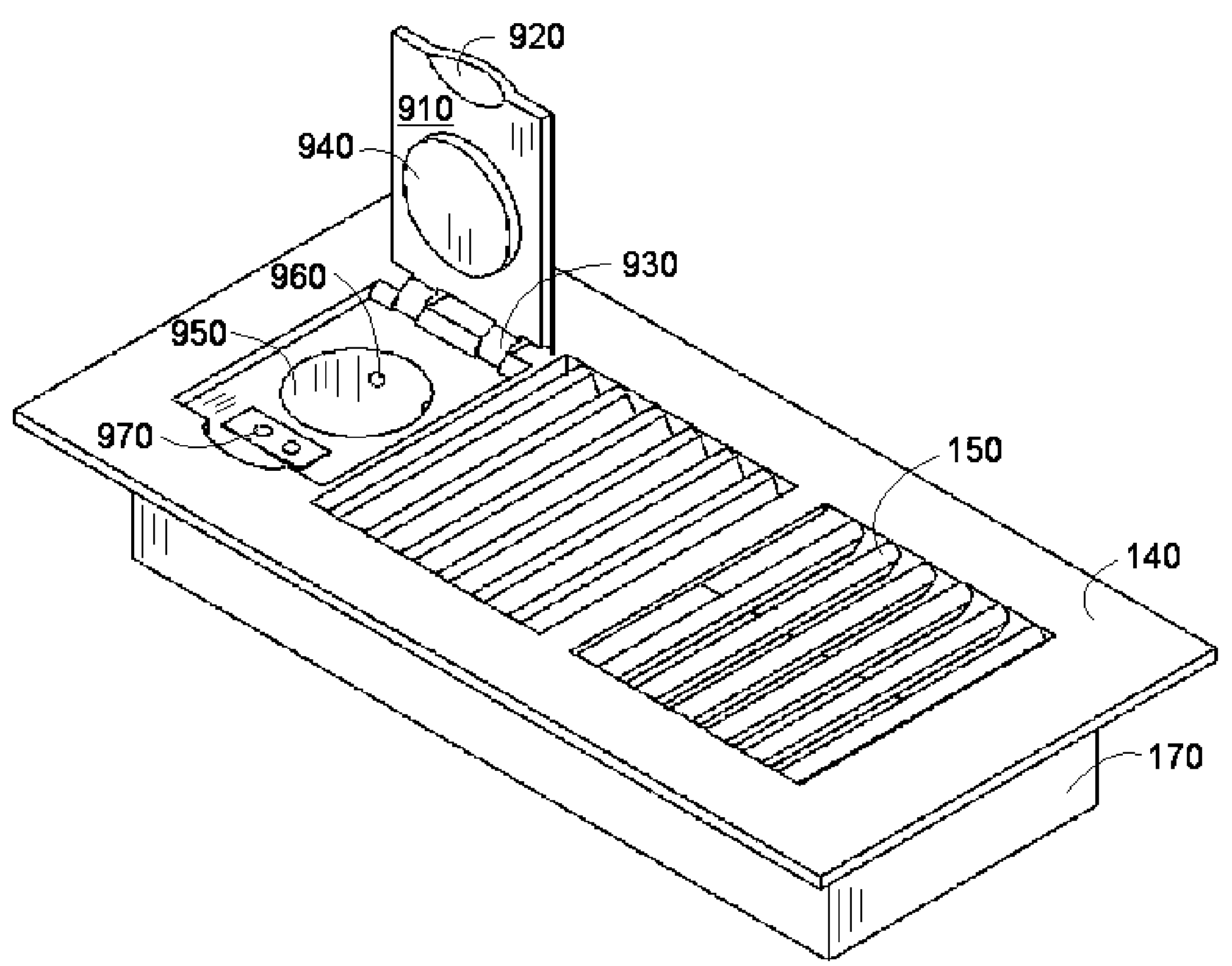
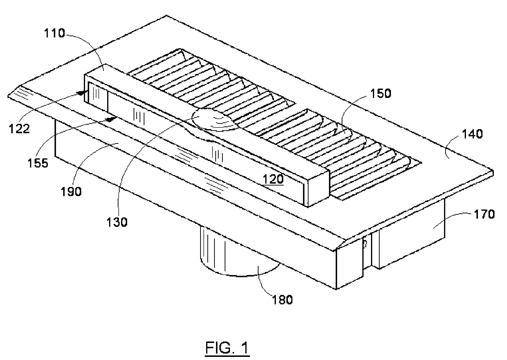
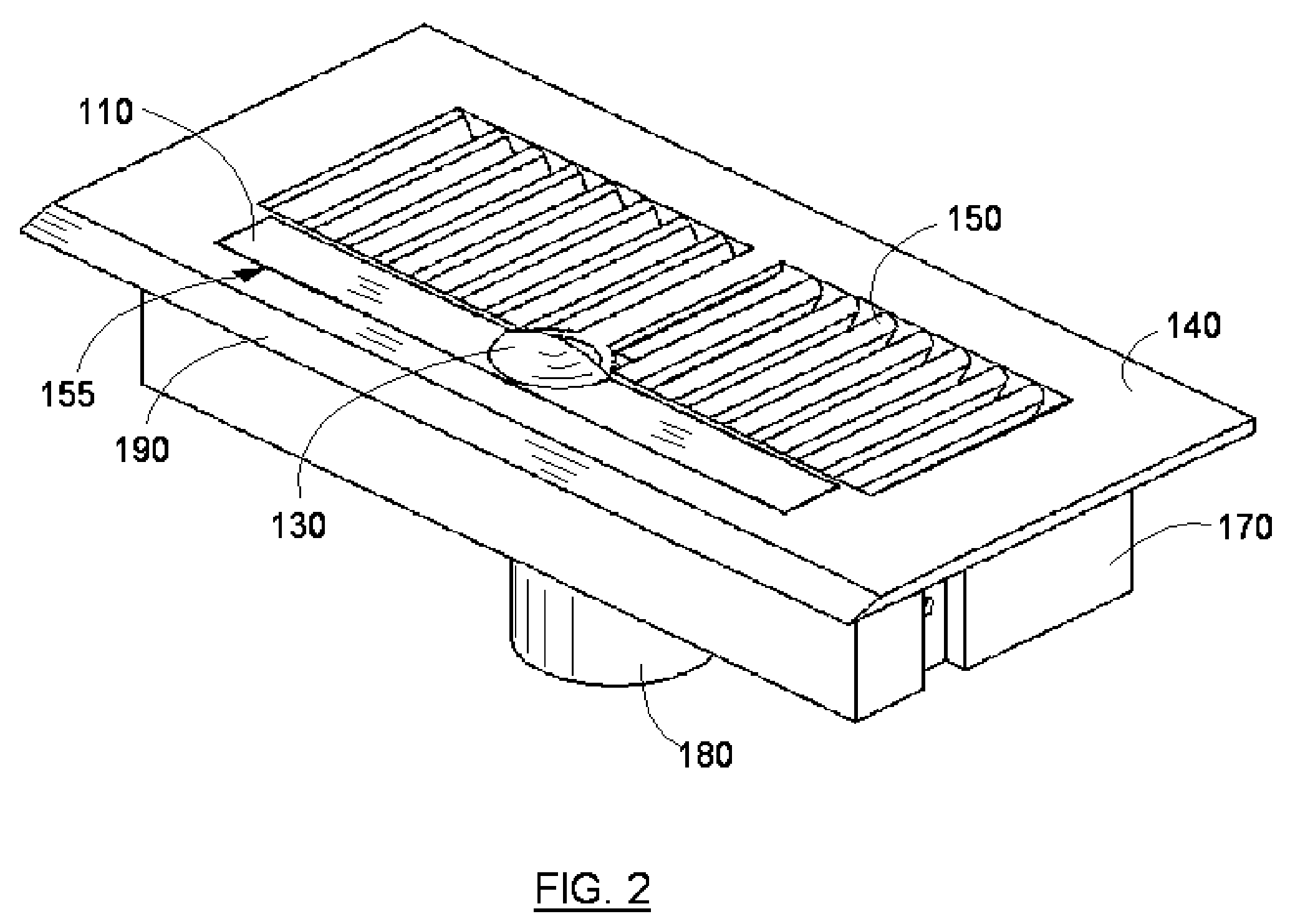
[0026]There is shown in FIGS. 1 and 2 a register 140 with a base 170 and illustrated air grills 150. The apparatus of this invention includes an inlet 110 which can be raised or lowered to open or close. The inlet 110 is shown in its open position in FIG. 1, and is shown in its closed position in FIG. 2. The register 140 is constructed with an opening 155 that will receive the inlet 110. The inlet 110 will have a means for lifting by way of a pull 130 such as the one illustrated. The inlet 110 will have a debris receiving chamber 120 with an opening 122 as illustrated for debris to enter. The register 140 will also have a beveled edge 190 to facilitate the movement of debris to the opening 122. It is assumed that the register 140 will also include standard regulators as commonly used to regulate the air flow through the register 140, but are not shown here in order to illustrate the inlet 110 features and integration into the register 140.

[0027]The assembly of the apparatus is illus...


PUM


Abstract

An inlet apparatus for central vacuum cleaning systems is described that can be integrated with registers commonly used with heating and air conditioning vents in residential or commercial buildings. In particular, the apparatus opens to provide a vacuum inlet that will either remove debris directly, or through an attached hose, using the suction provided by the connected conventional central vacuum cleaning system. The apparatus contains a register body and an inlet that can be integrated with the conventional pipe ductwork used for central vacuum cleaning systems. The apparatus will seal closed when not in use in order to provide full suction to any other inlet currently in use.

Description

BACKGROUND OF THE INVENTION[0001]This invention relates to central vacuum cleaning systems, specifically to an inlet that can be integrated with registers commonly used with heating and air conditioning vents in residential or commercial buildings.[0002]Central vacuum cleaning systems are becoming more common in residential housing and commercial buildings. Central vacuum cleaning systems are comprised of a main power and debris receptacle usually located in a remote location such as a basement or garage, a system of pipe ductwork which extends beneath the floor and between the walls to inlets located throughout the residential or commercial unit, and a hose with an assortment of wands or brush attachments. A provision is made for each inlet to automatically seal closed when not in use in order to provide full suction to any other inlet currently in use.[0003]Central vacuum cleaning systems have experienced growth in popularity due to many factors such as increased vacuum power, con...

Claims


Application Information

Patent Timeline
Patent Type & Authority Patents(United States)
IPC IPC(8): A47L5/38
CPCA47L5/38
Inventor JENKINS, BRADLEY E.
Owner JENKINS BRADLEY E
Why Eureka
Try Eureka