
Porous metal based composite material

a composite material and porous metal technology, applied in the direction of gearing, coatings, statators, etc., can solve the problems of difficult selection of foam materials for steel materials, difficult to provide an even structure, uneconomical powder metallurgy methods (1), etc., to achieve good thermal expansion coefficient, simple industrial application, and good economic

Inactive Publication Date: 2008-02-12
NGK INSULATORS LTD
View PDF17 Cites 0 Cited by
  • Summary
  • Abstract
  • Description
  • Claims
  • Application Information

AI Technical Summary

Benefits of technology

[0007]Accordingly, it is an object of the present invention to provide a porous composite material which has an excellent coefficient of thermal expansion, Young's modulus, proof stress and so forth, and in particular, a porous composite material that is simple for industrial applications and can be economically manufactured.
[0009]While focusing on this fact, the present inventors carried out various tests in order to solve the above-noted problems. Accordingly, a porous metal material including a metal material for forming a matrix and at least two fine particle material shaving different wettabilities with respect to the metal material is provided by melting and impregnating the metal material into the mixture of the at least two fine particle materials. The inventors found that the porous metal material is a composite material having an excellent balance of mechanical and physical characteristics that are different from those of the matrix metal, for instance, a characteristic balance between a low expansion coefficient and low proof stress, and so forth, thus completing the present invention.

Problems solved by technology

However, in consideration of these methods, including the aspect of making a metal-based composite material porous, the powder metallurgy method (1) is uneconomical although the manufacture of Ti or Ti alloy stainless steel has been attempted.
In this method, it is difficult to select a foam material for a steel material.
It is also difficult to provide an even structure by foaming a composite material of metal and non-metal or the like.
In the method (3), plastic is partially used as an organic material so that the application thereof is limited, which is troublesome.
However, since hot molten metal has to be pressured and injected into an inorganic material having a small density, there are restrictions on a manufacturing facility.
The method (5) presents difficulties in mass-production.

Method used


Image

  • Porous metal based composite material
  • Porous metal based composite material
  • Porous metal based composite material

Examples


example 1

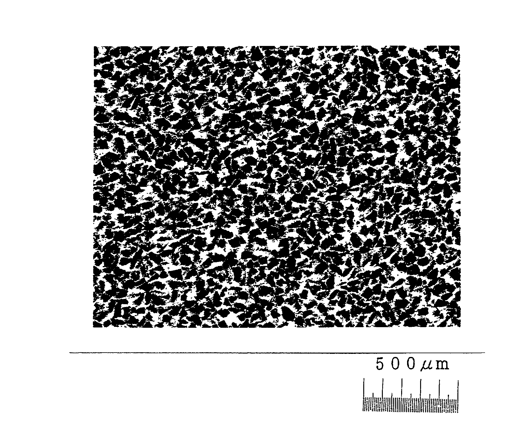
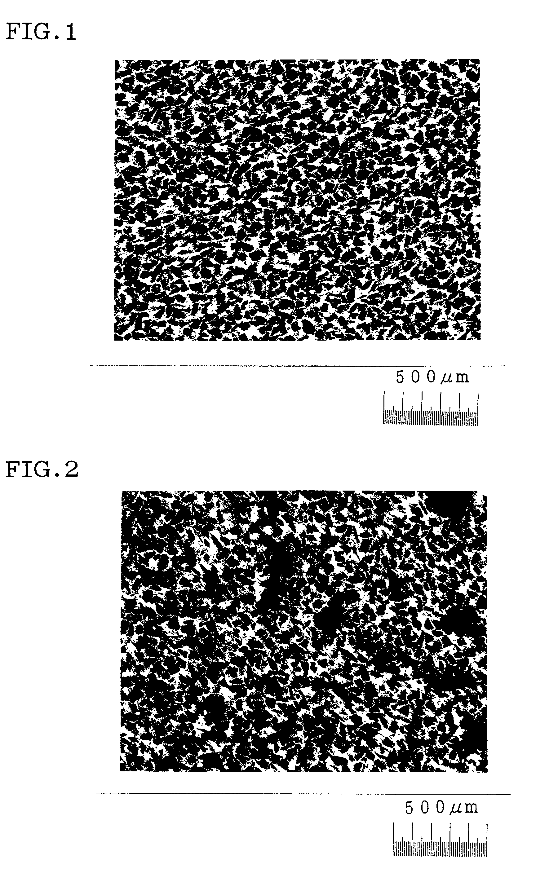
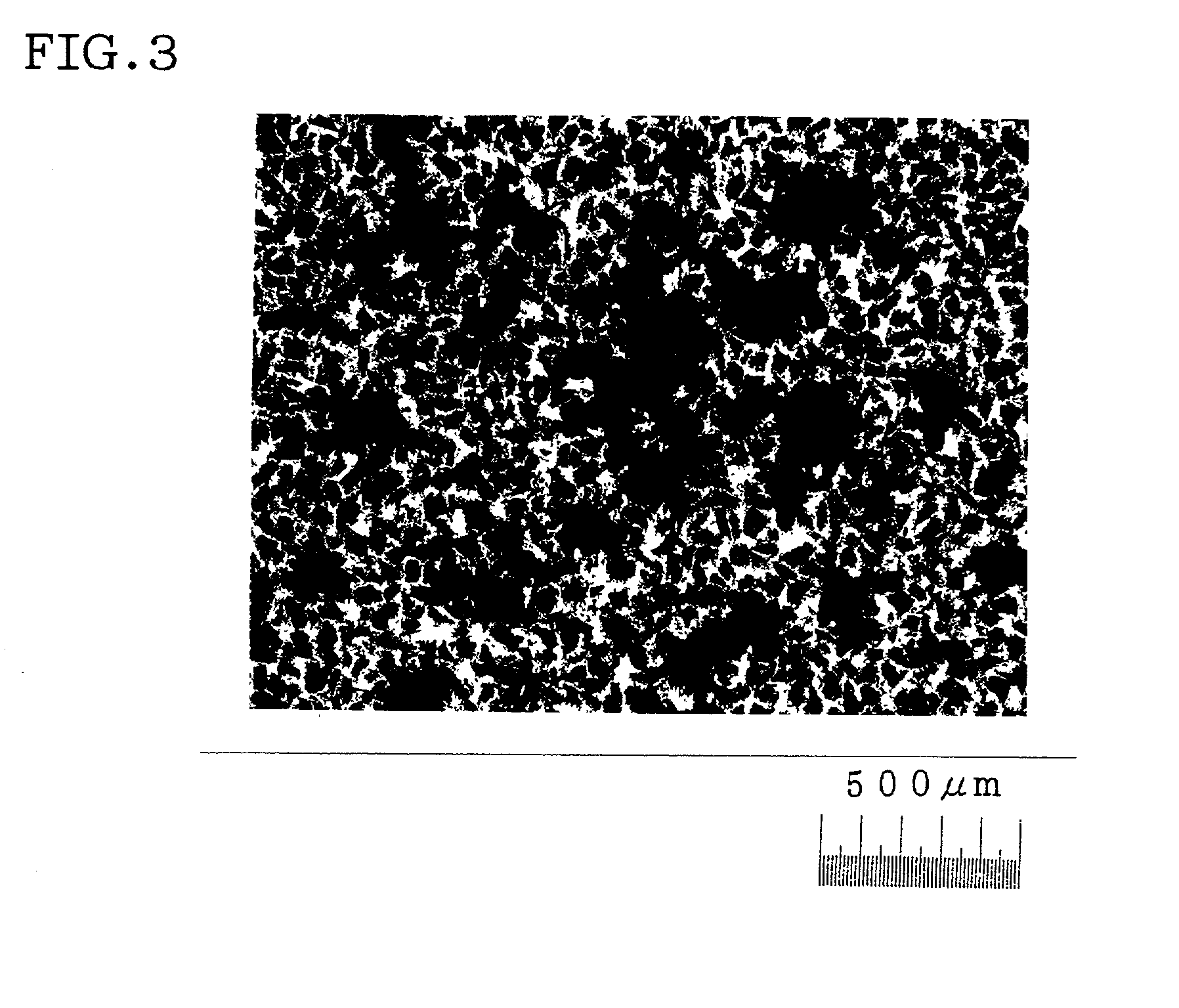
[0033]Alumina particles that were Ni-plated at a thickness of 0.3 μm on the surface thereof and had an average particle size of 50 μm, and alumina particles that were not surface treated and had an average particle size of 50 μm were mixed at each ratio of 1:0, 2:1, 1:1 and 1:2. The fine particles were mixed at each of the ratios and filled in a graphite jig. Subsequently, pure aluminum A1050 (Al>99.5%) or aluminum alloy A5005 (Al-0.8Mg) was arranged on the particles, was melted, penetrated into the particle mixture without pressure, and was solidified, thus providing a sample composite material. The mechanical and physical characteristics of the sample are shown in Table 1. In Table 1, the degree of penetration was determined by whether or not molten matrix metal penetrated evenly through the thickness of the layer of the fine particles filled in the jig.

[0034]FIG. 1, FIG. 2 and FIG. 3 are optical microscopic photographs, showing typical microstructures. FIG. 1 is an optical micros...

example 2

[0036]Alumina particles that were Ni-plated at the thickness of 0.3 μm on the surface thereof had an average particle size of 50 μm, and alumina particles that were not surface treated and had an average particle size of 50 μm, were mixed at the ratio of 2:1. Dispersion particles were mixed at the ratio and filled in a graphite jig. Subsequently, pure aluminum A1050 (Al>99.5%) or aluminum-magnesium alloy (Al-0.18 to 2.308Mg) was arranged on the particles, melted, penetrated into the particle mixture without pressure, and was solidified, thus providing a sample composite material. The mechanical and physical characteristics of the sample are shown in Table 2. In Table 2, the degree of penetration was determined by whether or not molten matrix metal penetrated evenly to the degree of penetration was determined by whether or not molten metal penetrated evenly through the thickness of the layer of the dispersion particles filled in the jig.

[0037]

TABLE 2MixingratioPlatingof platedYoung's...


PUM

PropertyMeasurementUnit
sizeaaaaaaaaaa
particle sizeaaaaaaaaaa

Abstract

A porous composite material includes a metal material for forming a matrix, and at least two kinds of fine particle materials having different wettabilities with respect to the metal material. The porous composite material is provided by melting and impregnating the metal material for forming a matrix with the mixture of at least two kinds of fine particle materials. The porous composite material has excellent characteristics in shock absorbency, acoustics, non-combustibility, lightness, rigidity, and so forth.

Description

BACKGROUND OF THE INVENTION[0001]1. Field of the Invention[0002]The present invention relates to a porous metal based composite material which requires no pressuring mechanism during manufacture due to the spontaneous penetration of a metal which will become a matrix, or which can be manufactured under low pressure even if pressure is required, and the characteristic control thereof.[0003]2. Description of the Related Art[0004]Known methods of manufacturing porous materials include: (1) powder metallurgy techniques to sinter metal powders or short fibers; (2) directly adding a foam material to molten metal; (3) plating on foam plastic and removing the plastic; (4) forming a compound from a material having a small density, such as a foam material, and a metal; and (5) blowing gas into molten metal under zero gravity, for example.[0005]However, in consideration of these methods, including the aspect of making a metal-based composite material porous, the powder metallurgy method (1) is...

Claims


Application Information

Patent Timeline
Patent Type & Authority Patents(United States)
IPC IPC(8): C22C21/00B22D19/00B22D19/14B22F1/02B22F3/11C22C1/08C22C1/10
CPCB22F3/114C22C1/1036C22C1/1015B22F1/0003B22F2999/00C22C2001/1021C22C1/1021B22F1/09B22F1/12
Inventor SHINKAI, MASAYUKIKIDA, MASAHIRO
Owner NGK INSULATORS LTD
Learn More