Method to suppress artifacts in frequency-domain optical coherence tomography

a technology of optical coherence tomography and frequency domain, applied in the field of optical imaging, can solve the problems of complex and costly sequential phase shift, add cost to frequency domain oct, and leave some residual image, etc., and achieve the effect of chromatic dispersion differen

Active Publication Date: 2008-02-12
CARL ZEISS MEDITEC INC
View PDF13 Cites 226 Cited by
  • Summary
  • Abstract
  • Description
  • Claims
  • Application Information

AI Technical Summary

Benefits of technology

[0018]One aspect of the present invention is to use the blurring effects of chromatic dispersion on OCT images to allow the viewer to distinguish the real image from the mirror image artifact in the resulting OCT tomogram, these blurring effects being corrected by multiplication by the complex phase factor only for the true, non-mirrored image.

Problems solved by technology

Since a perfect match of chromatic dispersion is not simple and can add cost to a frequency domain OCT system, numerical correction of the residual mismatch in chromatic dispersion has been described by Fercher et al.
In addition to chromatic dispersion match or correction, there are two additional major issues associated with this method.
Therefore, simple methods of frequency-domain OCT do not distinguish between scattering from a sample location corresponding to an optical group delay a certain amount longer than that of the reference path, and scattering with an optical group delay the same amount shorter than that of the reference path.
Phase shifting one of the interfering beams has been proposed to remove the mirror image in spectral domain OCT, but to date these methods leave some residual image and are complicated and costly (Leitgeb, R. A. et al., Optics Letters 28: 2201-2203; Izatt et al.
In particular, sequential phase shift does not produce a good result if the sample such as a human eye tends to move during the period when the multiple phase interference spectrums are recorded (Targowski et al., Optics Communications, 229:79-84).
On the other hand, simultaneous parallel multi-phase detection of the interference spectrum would require the use of at least two spectrometers or two detector arrays in the spectrometer, which will not only add complication in terms of optical alignment but also substantially increase the spectrometer cost.
In addition, it requires an additional optical frequency shifter which is an expensive item and hence would add cost to the OCT system.
The second issue is that when the interference spectrum is recorded as a function of optical frequency, periodic interfering signals as a function of optical frequency can corrupt the digitized spectrum.
For example, in the case of spectral-domain OCT, the readout electronics of the array detector often adds periodic pattern noise to the recorded optical intensities.
Furthermore, a spectral ripple of the light source, such as those caused by etalon effects from inadvertent reflections in path from the light source, causes a periodic error signal in the recorded interference spectrum.
The periodic error signal from these and similar sources is difficult to distinguish from the interference fringes caused by light scattered from the sample.
From the above discussions, it can be seen that previous frequency-domain OCT systems generally require a match in the chromatic dispersion characteristics of the two interferometer paths and even with a perfect match or a correction of the residual mismatch, the existing methods cannot cost-effectively address the issue of a mirror image and the artifacts induced by periodic spectral noise from either the source or the detector, there is hence a need in the art of frequency domain OCT to remove the stringent requirement of chromatic dispersion match, to easily and clearly distinguish the mirror image from the real image and to substantially suppress the image artifacts due to periodic spectral error signals.

Method used


Image

  • Method to suppress artifacts in frequency-domain optical coherence tomography
  • Method to suppress artifacts in frequency-domain optical coherence tomography
  • Method to suppress artifacts in frequency-domain optical coherence tomography

Examples


Embodiment Construction

[0032]Implementations of swept-source OCT are described by Swanson and Chinn (U.S. Pat. No. 5,956,355) and a modern implementation of spectral-domain OCT is described by Wojtkowski, et al. (Optics Express 12: 2404-2422). The common features of these two frequency-domain OCT techniques are reviewed here.

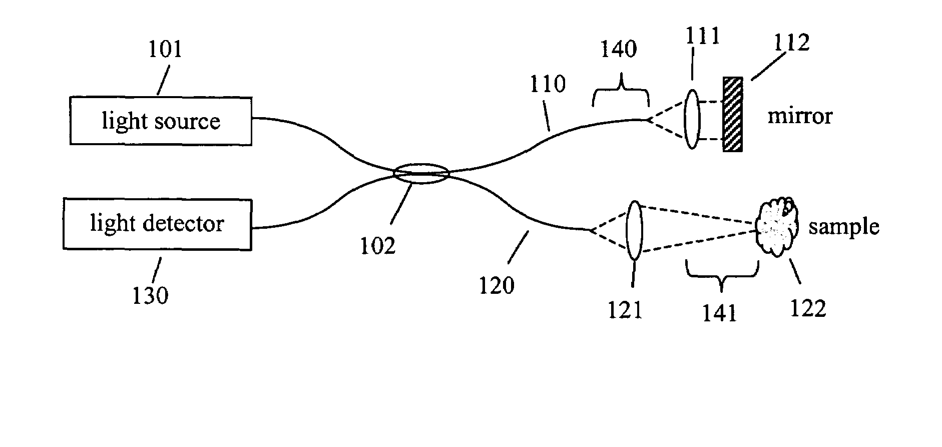
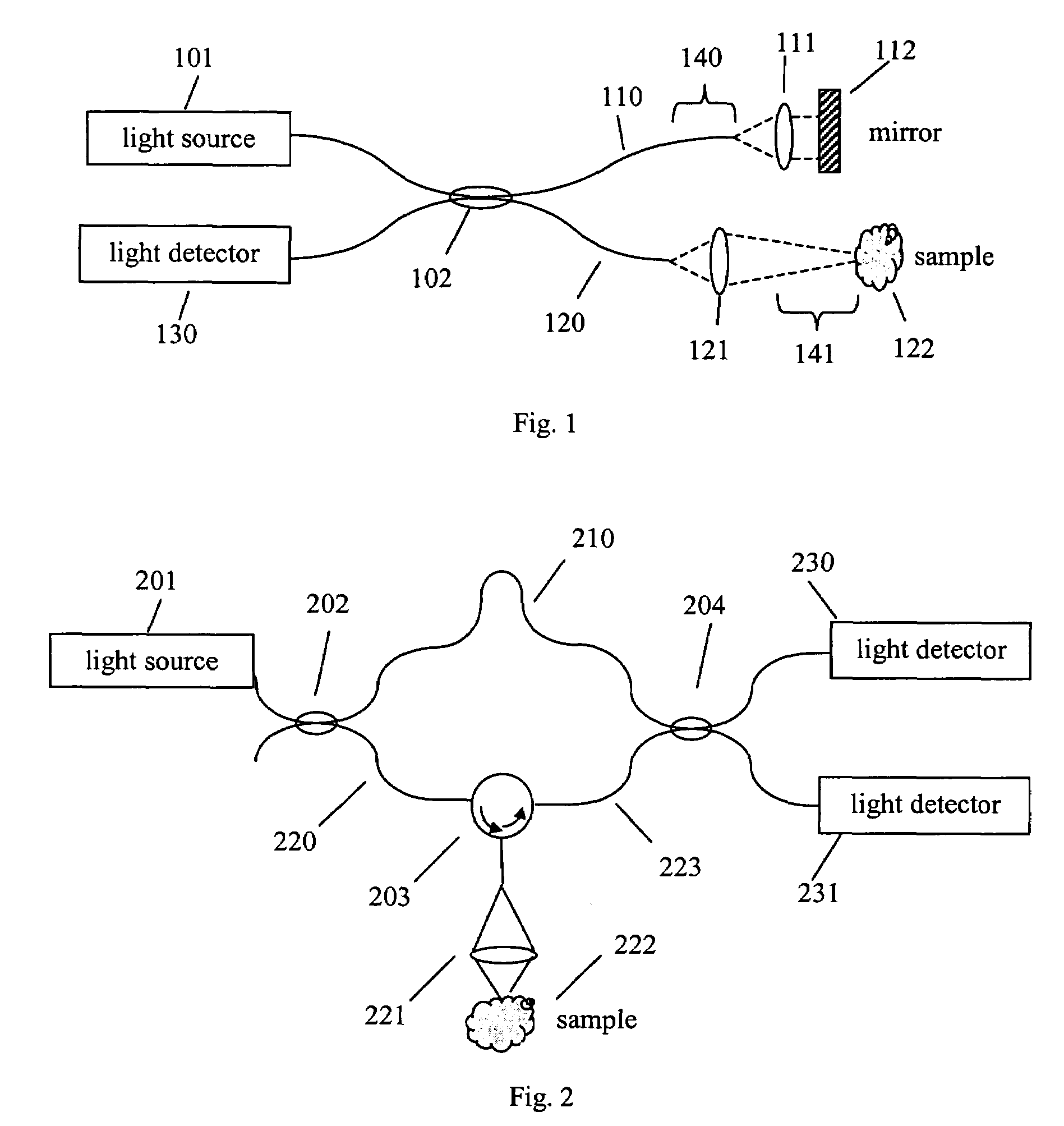
[0033]FIG. 1 illustrates an example of an OCT interferometer. Light from source 101 is directed to beamsplitter 102, illustrated here as a fiber beamsplitter, that separates light from the source between the reference fiber 110 and sample fiber 120. Some light directed toward sample 122 by lens 121 is scattered by the sample and returned through sample path 120. Some light collimated by lens 111 and reflected from the reference mirror 112 is returned through reference fiber 110. Light returned from the mirror is combined with light returned from the sample in beamsplitter 102 to form an interference signal, and some of the combined light is directed to the detector 130.

[0034]In freque...


PUM

PropertyMeasurementUnit
thicknessaaaaaaaaaa
optical path lengthaaaaaaaaaa

Abstract

One embodiment of the present invention is a method for suppressing artifacts in frequency-domain OCT images, which method includes (a) providing sample and reference paths with a significant difference in their chromatic dispersion (b) correcting for the effects of the mismatch in chromatic dispersion, for the purpose of making artifacts in the OCT image readily distinguishable from the desired image.

Description

PRIORITY[0001]This application claims the benefit of the filing date under 35 U.S.C. § 119(e) of Provisional U.S. Patent Application Ser. No. 60 / 645,791, filed on Jan. 21, 2005, and to Provisional U.S. Patent Application Ser. No. 60 / 714,721, filed on Sep. 7, 2005, which are hereby incorporated by reference in their entirety.TECHNICAL FIELD OF THE INVENTION[0002]One or more embodiments of the present invention relate generally to optical imaging, in particular, methods of frequency-domain optical coherence tomography (OCT) in which the interference signal is measured as a function of optical frequency. The invention is a novel method for suppressing artifacts in OCT images, and in blurring the mirror image present in images acquired by frequency-domain OCT so that it can be clearly distinguished from the real image.BACKGROUND OF THE INVENTION[0003]Optical Coherence Tomography (OCT) is a technology for performing high-resolution cross sectional imaging that can provide images of tissu...

Claims


Application Information

Patent Timeline
Patent Type & Authority Patents(United States)
IPC IPC(8): G01N21/90G01J3/45
CPCA61B5/0066A61B5/0073G01B9/02083G01B9/02091G01B9/02058G01B9/02078G01B9/0201A61B5/7257
Inventor O'HARA, KEITH E.HACKER, MARTIN
Owner CARL ZEISS MEDITEC INC
Why Eureka
Try Eureka