Microphone

a microphone and a technology for a microphone, applied in the direction of mouthpiece/microphone attachment, hose connection, machine support, etc., can solve the problems of unbalanced power line, noise generation, brittle shock shock, hard cured adhesive, etc., to improve assembling workability, fill easily, and improve bonding properties

Active Publication Date: 2008-02-12
AUDIO-TECHNICA
View PDF2 Cites 15 Cited by
  • Summary
  • Abstract
  • Description
  • Claims
  • Application Information

AI Technical Summary

Benefits of technology

[0016]According to this configuration, the flexible pipe and the connector are connected electrically to each other via the spacer formed of a metallic material having electric conductivity and spring-like elastic restoring force. Since a conductive adhesive is not used, the conductive resistance is low, so that stable continuity can be secured for a long period of time.
[0018]Since the elastic adhesive which has elasticity even after being cured is used as mechanical connecting means for connecting the connector to the flexible pipe, a shock mount effect for the microphone unit is achieved in the connecting portion, by which vibration noise can be reduced.
[0020]Since the mesh sheet made of the metallic wire is used as the spacer, a gap between the flexible pipe and the connector can be filled easily, and since the adhesive intrudes into the mesh sheet, the bonding properties are improved. Further, since one kind of adhesive is used, the assembling workability can be improved.

Problems solved by technology

Especially in the case of a condenser microphone, a signal line that is unbalanced with a power line is inserted as the electrical cable.
However, since metal powder such as silver is incorporated in the conductive adhesive, displacement after curing changes the electrical resistance, and thereby noise may be generated.
Also, the conductive adhesive has a property that the cured adhesive is very hard and brittle to shock.
However, because of high bonding strength, the epoxy adhesive has a problem as described below.

Method used


Image

  • Microphone
  • Microphone
  • Microphone

Examples


Embodiment Construction

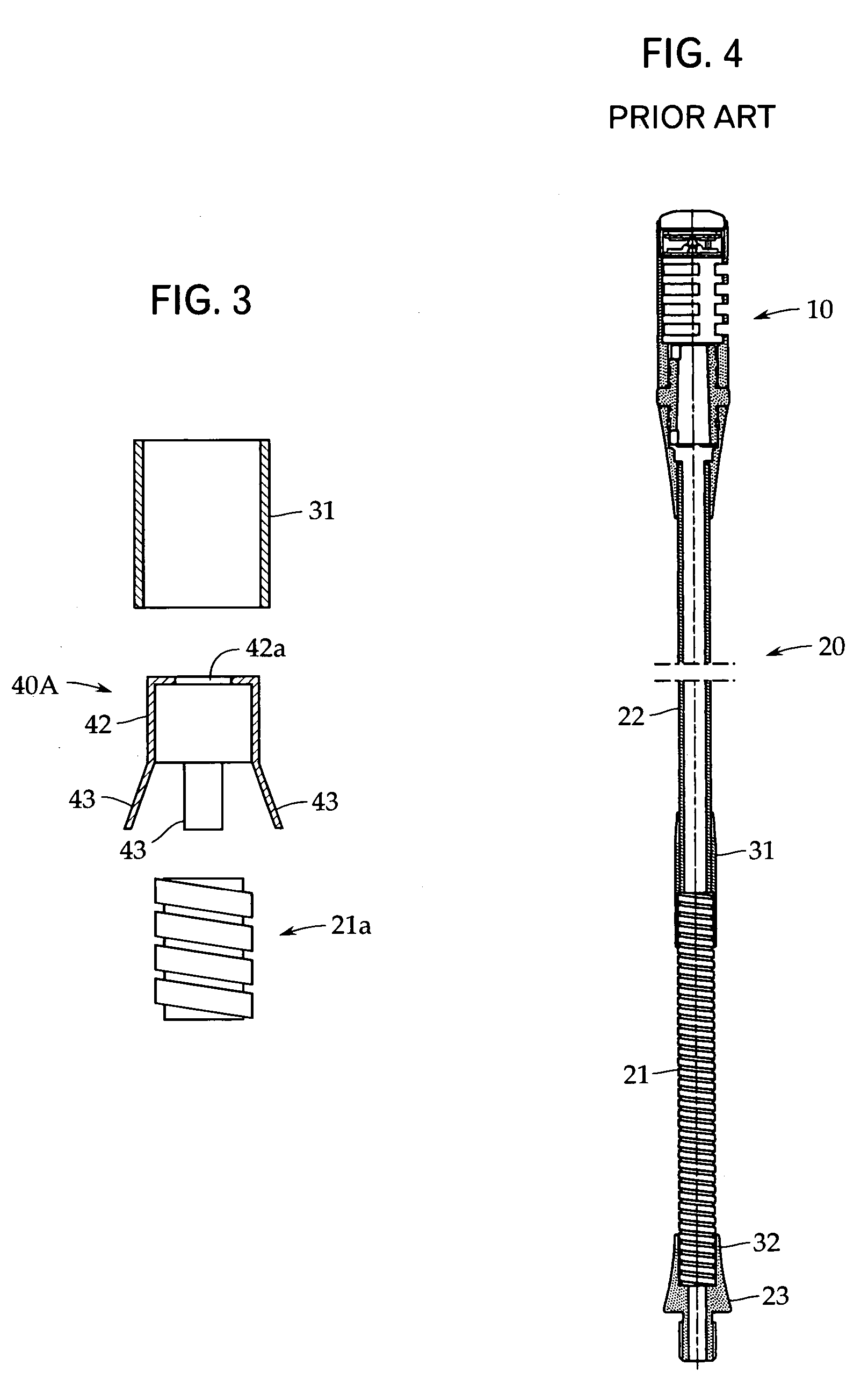
[0025]An embodiment of the present invention will now be described with reference to FIGS. 1 to 3. The present invention is not limited to this embodiment. In this embodiment, the same reference numerals are applied to elements that are the same or may be regarded as the same as those in the conventional example explained before with reference to FIG. 4.

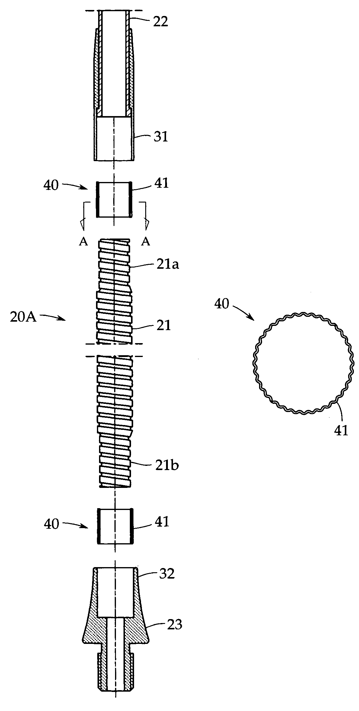
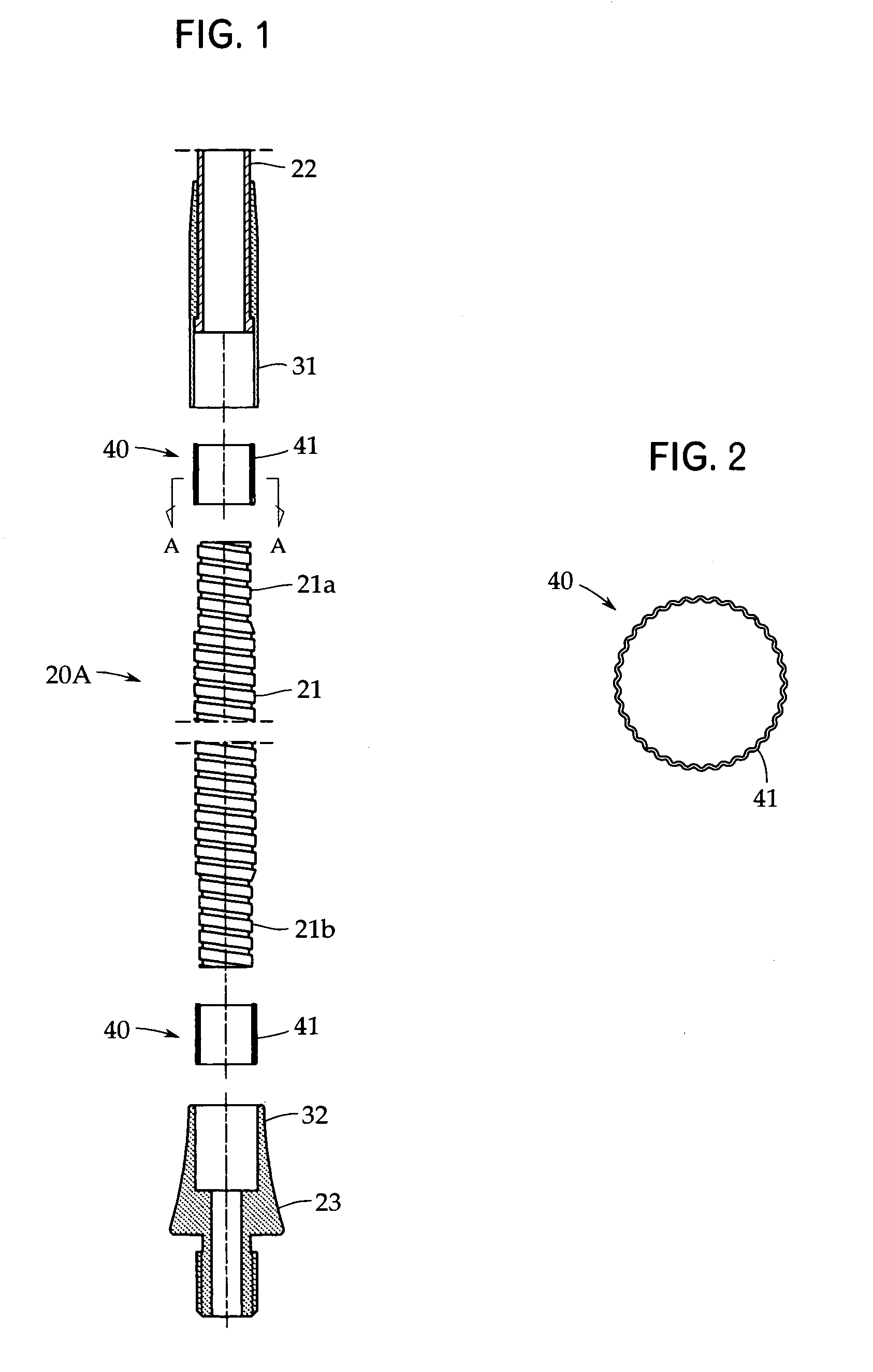
[0026]FIG. 1 is an exploded view of a column 20A that a microphone device in accordance with the present invention has as an essential portion. In this example, the column 20A includes a flexible pipe 21, a support pipe 22, and a rotating pedestal 23. These elements are connected in the order of the support pipe 22, the flexible pipe 21, and the rotating pedestal 23 from the upside, but may be connected in the order of the flexible pipe 21, the support pipe 22, and the rotating pedestal 23.

[0027]The flexible pipe 21 may be a commercially available one having the construction explained before in the conventional example. Although not ...


PUM


Abstract

In a gooseneck microphone device in which a microphone unit is supported by a column partially including a flexible pipe, the conductive resistance in a connecting portion of the flexible pipe is low, so that stable continuity can be secured for a long period of time, and vibrations are damped in the connecting portion of the flexible pipe. In connecting an end portion 21a of the flexible pipe 21 to a support pipe 22 via a connector 31, a spacer 40 (for example, a metallic mesh sheet 41) formed of a metallic material having electric conductivity and spring-like elastic restoring force is interposed in the connecting portion, and the flexible pipe and the connector are bonded to each other by an elastic adhesive which has elasticity even after being cured.

Description

TECHNICAL FIELD[0001]The present invention relates to a microphone device installed on a table, for example, in a conference hall. More particularly, it relates to a gooseneck microphone device in which a microphone unit is supported by a column partially including a flexible pipe.BACKGROUND ART[0002]Microphone devices are used properly according to their applications such as for music, conference, video camera, and the like. As one of the microphone devices used in a conference hall etc., a gooseneck microphone device has generally been used. FIG. 4 shows one example thereof.[0003]According to this example, for the gooseneck microphone device, a microphone unit 10 is installed on a table via a column 20 including a flexible pipe 21 and a metallic support pipe 22, so that the microphone unit 10 can be adjusted to a proper position with respect to a sound source (speaker) by the flexibility of the flexible pipe 21.[0004]In this example, the microphone unit 10 is held at the distal en...

Claims


Application Information

Patent Timeline
Patent Type & Authority Patents(United States)
IPC IPC(8): H04R25/00H04R1/00F16L27/10F16L33/34F16M11/40H04R1/08H04R19/04
CPCF16L27/10F16L33/34F16M11/40F16M11/28H04R1/08F16M2200/044H04R19/04F16M11/2014F16M13/00F16M13/02
Inventor AKINO, HIROSHI
Owner AUDIO-TECHNICA
Why Eureka
Try Eureka