
Seismic base isolation by electro-osmosis

a technology of electro-osmosis and seismic base, which is applied in the field of seismic base isolation, can solve the problems of enormous amount of energy released, accumulation of strain at the boundary, and complex earth ground motions experienced during earthquakes, and achieve the effect of quick dissipation of excess pore water pressure and speeding up the dissipation of pore water pressur

Inactive Publication Date: 2008-02-19
HOCKING GRANT
View PDF14 Cites 2 Cited by
  • Summary
  • Abstract
  • Description
  • Claims
  • Application Information

AI Technical Summary

Benefits of technology

This approach effectively reduces structural damage by preventing the upward propagation of shear wave ground motions and can be implemented with minimal disruption to existing structures, providing a high degree of protection against earthquake-induced vibrations.

Problems solved by technology

In certain parts of the world, continuous differential movement occurs between one section of the earth's crust and an adjacent one, causing an accumulation of strain at the boundary.
When the stresses caused by this strain accumulation exceed the strength of the earth's materials, a slip occurs between two portions of the earth's crust and tremendous amounts of energy are released.
Earth ground motions experienced during an earthquake are actually quite complex due to the variation in the earth's crust, from strong stiff bedrock to soft weak soils.
Although the actual wave pattern may be very complex, the resulting ground motion imposed on the soil and the overlying structure are predominantly from the upward propagation of the S-wave components from the underlying bedrock.
Such amplification of earthquake induced ground motions can cause extensive damage to buildings, bridges, pipelines, embankments, dams, slopes, and other structures and works constructed on soft soil deposits.
Structures constructed on such soils can be extensively damaged by even a moderate size earthquake.
The 1985 Michoacan earthquake caused only moderate damage in the vicinity of its epicenter but caused extensive damage to structures located on a thick deposit of soft silts and clay some 350 km away in Mexico City.
Likewise, the 1989 Loma Prieta earthquake caused minor damage in the vicinity of its epicenter but caused moderate to extensive damage to structures located on the San Francisco Bay mud some 100 km away.
Bearing isolation systems have in some circumstances, e.g. the 1994 Northridge (Calif.) earthquake, demonstrated to provide poor if any base isolation of the structure from the earthquake induced ground motion.
The mass damping systems have demonstrated some protection of a structure due to earthquake vibrations; however, they are expensive, and difficult to implement in existing structures.
The energy absorbing sliding bearing systems can be implemented in existing structures; however, their performance during actual earthquake events appear limited in isolating the structure from earthquake induced ground motions and minimizing structural damage.
Although the actual wave pattern may be very complex, the resulting repeated and reversing shearing deformations, imposed on the soil by the S-wave components are the principal cause of a phenomenon known as liquefaction, which occurs in saturated fine sand, silty sand and silt deposits.
Fine cohesionless soils, fine sand or fine cohesionless soils containing moderate amounts of silt are most susceptible to liquefaction.
The laboratory methods require undisturbed soil samples which are difficult to impossible to obtain.
At the present time, there is not a method for obtaining undisturbed samples, in which the in situ stress state, void ratio or structure have been preserved in cohesionless soils.
Electro-osmosis is not used extensively due to the high cost of maintaining the dc potential over long periods of time and the drying out and chemical reactions that occur if the system is activated for long periods of time.

Method used


Image

  • Seismic base isolation by electro-osmosis
  • Seismic base isolation by electro-osmosis
  • Seismic base isolation by electro-osmosis

Examples


Embodiment Construction

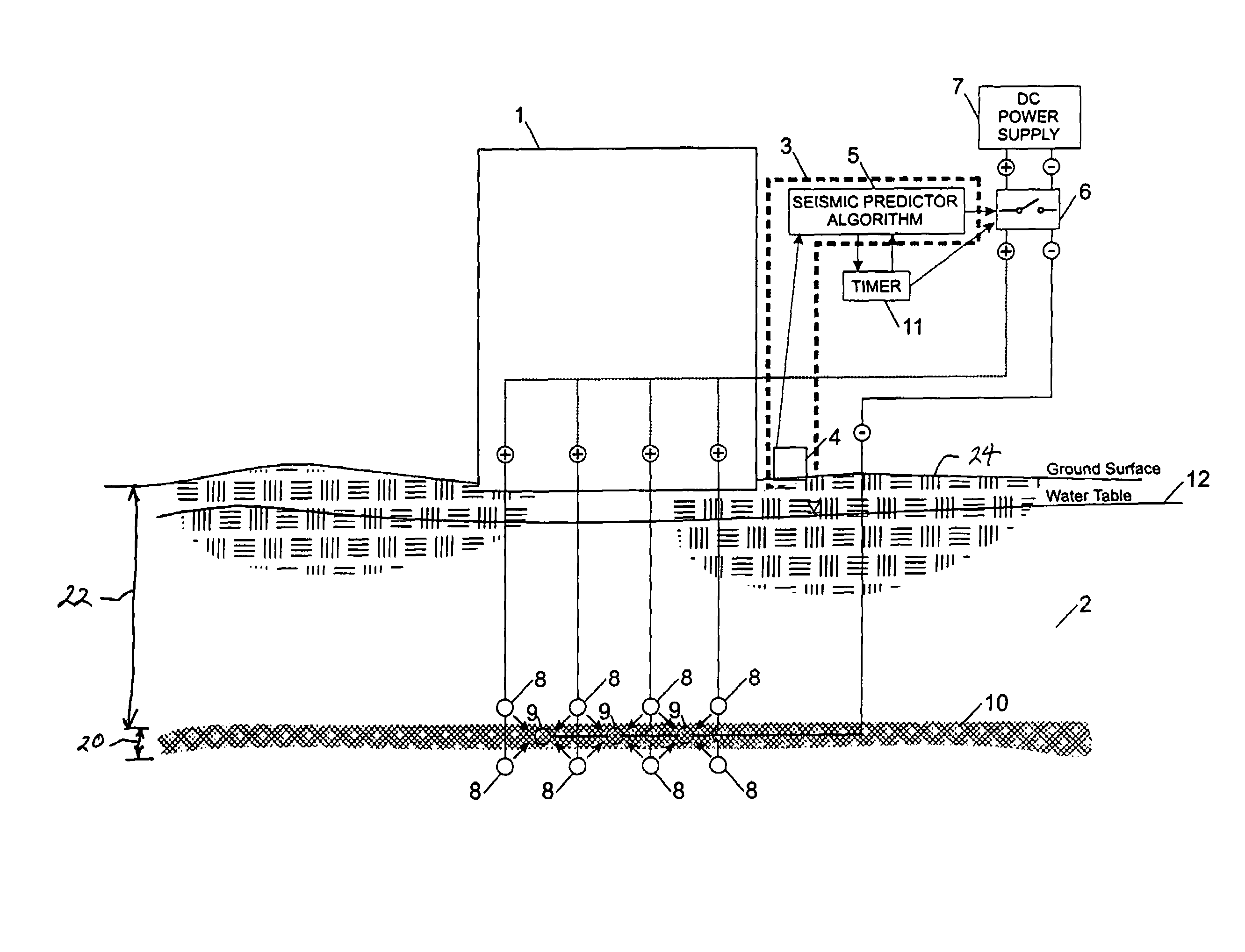
[0036]The present invention provides a method and system for seismically isolating a structure or works from earthquake induced ground motions. The method and system of the present invention employes a seismic monitor which activates a electro-osmosis system in the sub-surface saturated soils well beneath the structure. The electro-osmosis system raises the pore water pressure within a particular isolation layer of the soil horizon to ensure that soil horizon within that isolation layer liquefies during the earthquake event and thus isolates the overlying structure from the earthquake induced upward propagating shear wave ground motions. One form of the invention is illustrated in cross section in FIG. 1, with a structure 1 constructed on a saturated soil 2 which is prone to amplify earthquake induced ground motions. A seismically triggered switch 3 comprises an accelerometer 4 and predictor algorithm 5 running on a computer. The accelerometer 4 engages the ground surface 24 in orde...


PUM


Abstract

A structure is isolated from a seismic event by inducing soil liquefaction in an isolation layer beneath the structure and soil foundation zone, such as by activating an electro-osmosis gradient toward the isolation layer, during the seismic event, based on detection of movements associated with the seismic event.

Description

CROSS-REFERENCE TO RELATED APPLICATIONS[0001]This application is a continuation of U.S. patent application, Ser. No. 10 / 236,884 filed Sep. 5, 2002, which is now U.S. Pat. No. 6,792,720, issued Sep. 21, 2004, which is relied on and incorporated herein by reference.TECHNICAL FIELD[0002]This invention relates to seismic base isolation of a structure or soil mass from the vibratory motion generated during an earthquake, and more particularly to the preferential inducement of localized soil liquefaction of a particular isolation layer in the soil horizon beneath the structure by applying an electro-osmotic gradient to the saturated soil during the earthquake event and thus raising the pore water pressure to induce localized soil liquefaction within a particular isolation layer in the soil horizon which thus reduces the upward propagation of the earthquake induced shear wave ground motions to the overlying structure.BACKGROUND OF THE INVENTION[0003]Earthquakes are caused by the resultant ...

Claims


Application Information

Patent Timeline
Patent Type & Authority Patents(United States)
IPC IPC(8): E02D3/11E02D27/34E04H9/02E04BE04B1/00E04B1/98G01V1/00G01V7/00
CPCE02D3/11E02D27/34G01V1/008Y10S52/12G01V1/01
Inventor HOCKING, GRANT
Owner HOCKING GRANT
Learn More