Vibration reduction apparatus for power tool and power tool incorporating such apparatus

a technology of vibration reduction and power tools, which is applied in the direction of manufacturing tools, percussive tools, portable drilling machines, etc., can solve the problems of limited effectiveness of such materials in reducing the transmission of vibrations to the user of the apparatus, damage to the apparatus itself, and harm to the users of the apparatus, so as to achieve a more compact construction and reduce the effect of twisting torqu

Active Publication Date: 2008-02-19
BLACK & DECKER INC
View PDF29 Cites 50 Cited by
  • Summary
  • Abstract
  • Description
  • Claims
  • Application Information

AI Technical Summary

Benefits of technology

[0015]According to an aspect of the present invention, there is provided a vibration reduction apparatus for a power hammer apparatus comprising a housing, a motor arranged in the housing, a piston adapted to be caused by the motor to execute reciprocating motion in a bore, and a flying mass arranged in the bore such that said reciprocating motion of said piston in said bore in use causes reciprocating motion of said flying mass relative to the housing to impart impacts to a working member of the hammer apparatus, the vibration reduction apparatus comprising at least one driveable mass adapted to at least partially surround at least part of the bore, and wherein at least one said driveable mass is adapted to be caused by the m

Problems solved by technology

However, known hammer drills of this type suffer from the drawback that the hammer action generates significant vibrations, which can be harmful to users of the apparatus, and can cause damage to the apparatus itself.
However, the effectiveness of such materials in reducing the transmission of vibrations to the user of the apparatus is limited.
However, it has not to da

Method used


Image

  • Vibration reduction apparatus for power tool and power tool incorporating such apparatus
  • Vibration reduction apparatus for power tool and power tool incorporating such apparatus
  • Vibration reduction apparatus for power tool and power tool incorporating such apparatus

Examples


sixth embodiment

[0114]Referring to FIG. 7, in which parts common to the embodiment of FIG. 6 are denoted by like reference numerals but increased by 100, a vibration reduction mechanism 601 of the present invention has a cam 633 which is normally rigidly locked to gear wheel 623 by means of a pin 640 which is urged downwards as shown in FIG. 7 by means of torsional spring 641 which in turn urges a ball bearing 642 outwards of the pin 640 to lock the cam plate 633 to the gear wheel 623.

[0115]In order to deactivate the vibration reduction mechanism 601, pin 638 is urged to the left as shown in FIG. 7 against the action of compression spring 643 to move pin 640 upwards so that ball bearing 642 can be accommodated in narrowed portion 644 of pin 640. As a result, cam 633 can rotate freely on gear wheel 623, as a result of which the cam 633 does not displace cam follower 634. The counterweight 621 therefore does not move relative to piston cylinder 630.

seventh embodiment

[0116]the invention is shown in FIG. 8, in which parts common to the embodiment of FIG. 7 are denoted by like reference numerals but increased by 100. The vibration reduction mechanism 701 has a counterweight 721 provided in a chamber 750 adjacent to piston cylinder 730. Hammer piston 720 is driven reciprocally by means of wobble plate 751 mounted to drive shaft 752 (the drive shaft 752 being connected to the motor), and displacement of hammer piston 720 within piston cylinder 730 causes displacement of air in piston cylinder 730 and channel 753 connecting piston cylinder 730 and chamber 750 such that counterweight 721 is caused to move generally in antiphase with hammer piston 720.

[0117]Referring to FIG. 9, in which parts common to the embodiment of FIG. 7 are denoted by like reference numerals but increased by 200, a cam 833 is mounted to a gear plate 823, and a cam follower 834 is mounted to pivot arm 860. Pivot arm 860 pivots about pivot pin 861 and is urged by spring 835 into e...

ninth embodiment

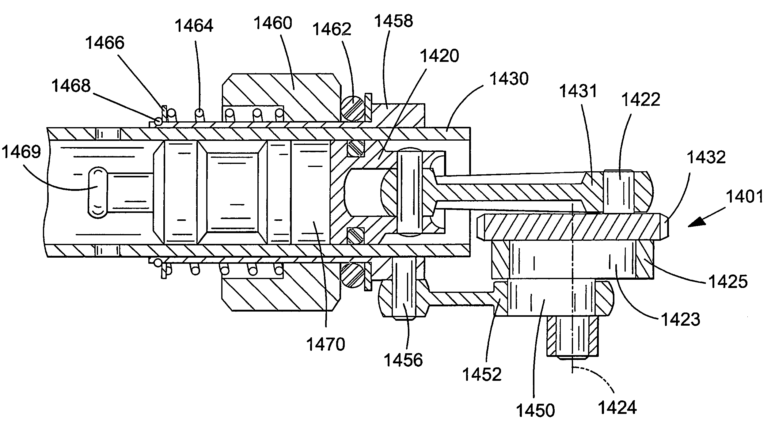
[0119]A compact vibration reduction mechanism 901 of the present invention is shown in FIG. 10, in which parts common to the embodiment of FIG. 9 are denoted by like reference numerals but increased by 100. A hammer piston 920 is driven by means of gear plate 923 having gear teeth 932 engaged by gear 914 on drive shaft 911. A cam 933 is rigidly mounted to gear wheel 923 and is engaged by the internal surface of a cam follower plate 934. Cam follower plate 934 is connected via pin 970 to counterweight 921, which forms part of piston cylinder 930 such that rotation of cam 933 causes oscillation of counterweight 921 in an axial direction.

[0120]In order to deactivate vibration reduction apparatus 901, cam follower plate 934 is displaced downwards as shown in FIG. 10 to disengage cam surface of cam follower plate 934 from cam 933. In this way, rotation of gear plate 923 does not cause axial movement of counterweight 921.

[0121]Referring to FIG. 11, in which parts common to the embodiment ...


PUM

PropertyMeasurementUnit
Massaaaaaaaaaa
Responsivityaaaaaaaaaa

Abstract

A vibration reduction apparatus for use with a hammer tool having a hammer piston is disclosed. The hammer piston is caused to reciprocate in the cylinder by rotation of a gear wheel and crank drive. A cam is mounted around the gear wheel, a counterweight surrounds the piston cylinder, and a cam follower is provided on the counterweight. The cam follower on the counterweight is urged into contact with the cam by a biasing element. The external profile of the cam is such that rotation of the gear wheel causes oscillation of the counterweight in anti-phase to motion of the hammer piston to counteract vibrations produced by operation of the hammer action of the tool.

Description

FIELD OF THE INVENTION[0001]The present invention relates to a vibration reduction apparatus for a power tool and to a power tool incorporating such apparatus. The invention relates particularly, but not exclusively, to vibration reduction apparatus for powered hammers, and to hammers incorporating such apparatus.DESCRIPTION OF THE RELATED ART[0002]Electrically driven hammers are known in which a driving member in the form of a flying mass is reciprocally driven in a piston, and impact of the flying mass against the end of the piston imparts a hammer action to a bit of the hammer. Such an arrangement is disclosed in European patent application EP1252976 and is shown in FIG. 1.[0003]Referring in detail to FIG. 1, the prior art demolition hammer comprises an electric motor 2, a gear arrangement and a piston drive arrangement which are housed within a metal gear housing 5 surrounded by a plastic housing 4. A rear handle housing incorporating a rear handle 6 and a trigger switch arrange...

Claims


Application Information

Patent Timeline
IPC IPC(8): B25D11/00B25D17/06B25D17/24
CPCB25D11/062B25D17/06B25D17/24F16F15/22B25D2211/061B25D2211/068B25D2217/0084B25D2217/0092B25D2250/045B25D2250/185B25D2250/221B25D2250/231B25D2217/0088
Inventor STIRM, MICHAELFAATZ, HEINZ-WERNER
Owner BLACK & DECKER INC
Why Eureka
Try Eureka