Method for compressing the working fluid during a water/steam combination process

a technology of working fluid and water/steam, which is applied in the direction of steam engine plants, jet propulsion plants, engine fuctions, etc., can solve the problems of increasing the mass flow of working fluid

Inactive Publication Date: 2008-02-19
RERUM COGNITIO GES FUR MARKTINTEGRATION DEUTER INNOVATIONEN & FORSCHUNGSPROD
View PDF9 Cites 7 Cited by
  • Summary
  • Abstract
  • Description
  • Claims
  • Application Information

AI Technical Summary

Benefits of technology

[0005]The coolant is preferably supplied to the working fluid in such a quantity that the thermal equilibrium is maintained. In this connection, the evaporation of the coolant takes place along the saturation curve. The addition of coolant quantities between the compressor inlet and the compressor outlet results directly in an increase in the working fluid mass flow. The process engineering measures mentioned give rise to a number of desirable technical effects at the same time. By virtue of the evaporation heat required for the evaporation of the coolant being taken directly from the compression process, a reduction in the temperatures of compressed working fluid and technical apparatus is brought about. Parallel to this, the mass flow through the compressor is increased, and a reduced compressor power is required. The steam turbine operating on the same shaft can consequently deliver an increased net power.

Problems solved by technology

The addition of coolant quantities between the compressor inlet and the compressor outlet results directly in an increase in the working fluid mass flow.

Method used


Image

  • Method for compressing the working fluid during a water/steam combination process
  • Method for compressing the working fluid during a water/steam combination process

Examples


Embodiment Construction

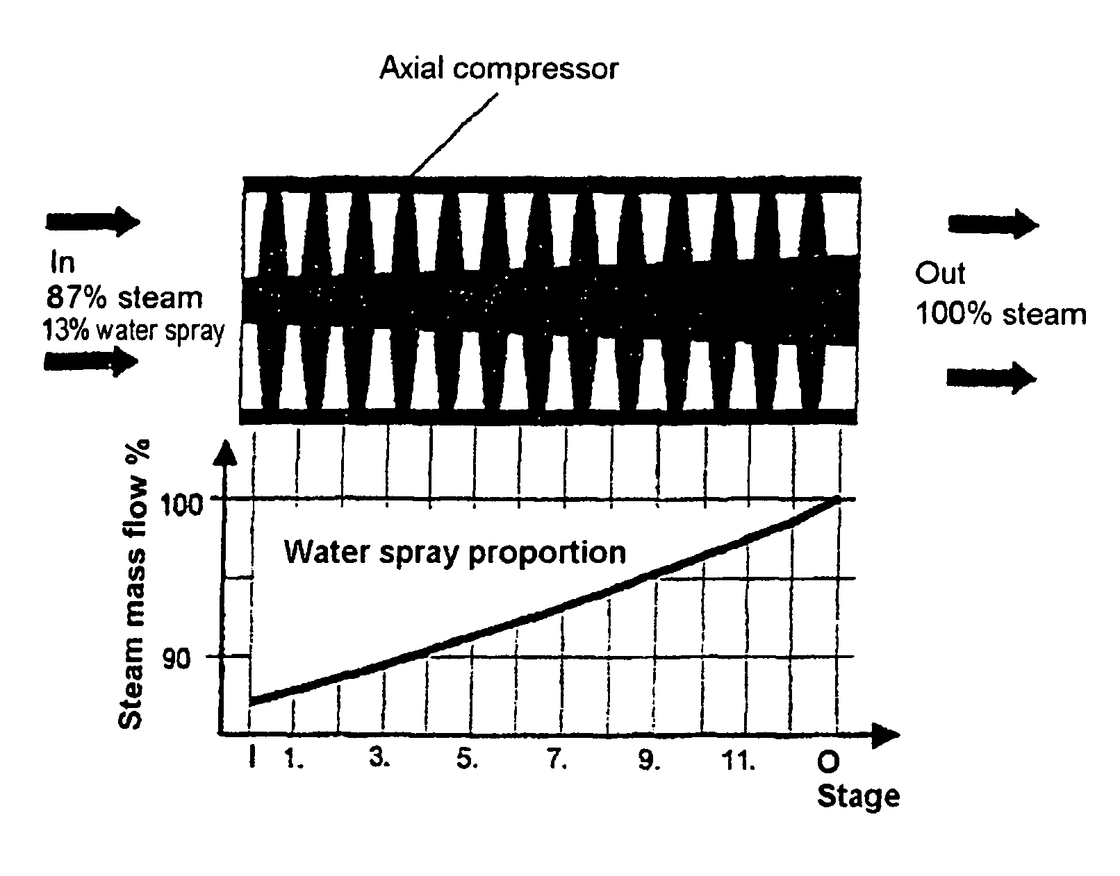
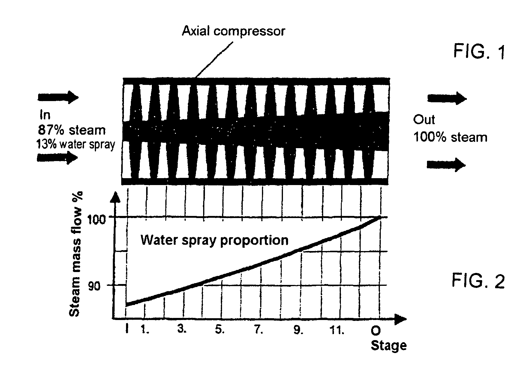
[0013]According to FIGS. 1 and 2, the expanded water vapour leaving the steam turbine is, in a WDK process, supplied to a turbocompressor arranged on the common shaft to be compressed again. The turbocompressor has 13 compression stages. Before the working fluid enters the turbocompressor, coolant is added to the working fluid in a ratio of 0.15 mass parts coolant to 1 mass part working fluid. In this connection, the coolant consists of a water spray, which is obtained by atomizing steam condensate. The diameters of the individual droplets of the water spray are smaller than 25 μm. Owing to the compression in stages of the mixture consisting of steam and water spray, a virtually continuous temperature increase, which runs parallel to the reduction of the coolant proportion in the overall mass flow, is achieved over the individual compression stages until the compressed working fluid leaves the turbocompressor. The compressed working fluid then returns to the steam turbine. The mecha...


PUM


Abstract

A method for compressing the working fluid during a water / steam combination process in multi-stage turbocompressors comprising intercooling in the individual compressor stages, by the addition of a coolant to the working fluid. The aim of the invention is to provide a technical solution, which is suitable for the efficient intercooling of the working fluid during multi-stage compression and thus for the highest possible reduction of the required compressor power. To achieve this, dispersed water, which is obtained by the pressure atomization of water to form micro-droplets, is used as the coolant. The coolant is added directly to the working fluid in at least one compression stage in a quantity that maintains the thermodynamic equilibrium, and is converted during compression into the state of the working fluid, the evaporation of the coolant takes place at the saturation line. The addition of coolant between the compressor entrance and the compressor exit permits the mass flow of the working fluid to be increased.

Description

BACKGROUND OF THE INVENTIONField of the Invention[0001]The invention relates to a method for compressing the working fluid in a combined cycle water / steam process in multi-stage turbocompressors with intercooling in the individual compression stages by addition of a coolant to the working fluid. Such a technical solution is required in the production of useful energy by means of combined cycle water / steam processes.[0002]It is known that intercooling during the compression of the working fluid in turbocompressors reduces the compressor power required. It is known from gas turbine technology (J. van LIERE / C. G. MEIJER / G. H. M. LAAGLAND: Leistungssteigerung und Nox-Reduktion der Gasturbinen durch SwirlFlash®-Overspray-Eindüsung [Power increase and Nox reduction in gas turbines by SwirlFlash® overspray injection], VGB PowerTech 2 / 2002) to mobilize power reserves by reducing the compressor power by virtue of coolant addition during gas compression. For this purpose, finely atomized wate...

Claims


Application Information

Patent Timeline
Patent Type & Authority Patents(United States)
IPC IPC(8): F01D25/12F01K25/00F04D29/58F04D31/00
CPCF01K25/005F04D29/5846F04D31/00F05B2260/211F05B2260/212
Inventor HARAZIN, WOLFGANG
Owner RERUM COGNITIO GES FUR MARKTINTEGRATION DEUTER INNOVATIONEN & FORSCHUNGSPROD
Why Eureka
Try Eureka