Method and device for calculating a biological component density of a subject

a biological component and density technology, applied in the field of methods and devices for calculating the density of biological components of subjects, can solve the problems of difficult to carry out easy and correct measurement to each subject with big individual differences, subject preparation and calibration equations have to have heavy burden, etc., to achieve easy operation to the skin of subjects, and accurate measurement of biological component density

Active Publication Date: 2008-02-19
PHC HLDG CORP
View PDF9 Cites 31 Cited by
  • Summary
  • Abstract
  • Description
  • Claims
  • Application Information

AI Technical Summary

Benefits of technology

[0011]It is preferable that the incident guide has a light projecting end adapted to be held in close proximity to the skin, and the reflective guide has a light receiving end adapted to be held in close proximity to the skin, and the light receiving end is spaced from the light projecting end by a distance of 2 mm or less across the skin. By such disposition, it becomes possible to obtain the NIR spectrum which passed and reflected subsequently the dermal organization which is supposed to reflect most the biological component to be calculated. Therefore, the measurement of the biological component density can be made accurately.
[0012]In a preferred embodiment, the incident guide and the reflective guide are made respectively by optical fibers, and they are integrated into a single probe head having an object end to which the light projecting end and the light receiving end are exposed. Consequently, the operation to the skin of the subject becomes easy.
[0013]It is also preferable that the prove includes a plurality of different incident guides and a single reflective guide, and the different incident guides have individual light projecting ends which are spaced by different distances, respectively from the light receiving end. The light source is selectively

Problems solved by technology

However, preparing the calibrating equations for each individual or each measurement part requires to restrain people or living things as measuring objects for a long time to prepare the calibrating equations by multivariate analysis of the NIR spectrum data

Method used


Image

  • Method and device for calculating a biological component density of a subject
  • Method and device for calculating a biological component density of a subject
  • Method and device for calculating a biological component density of a subject

Examples


first embodiment

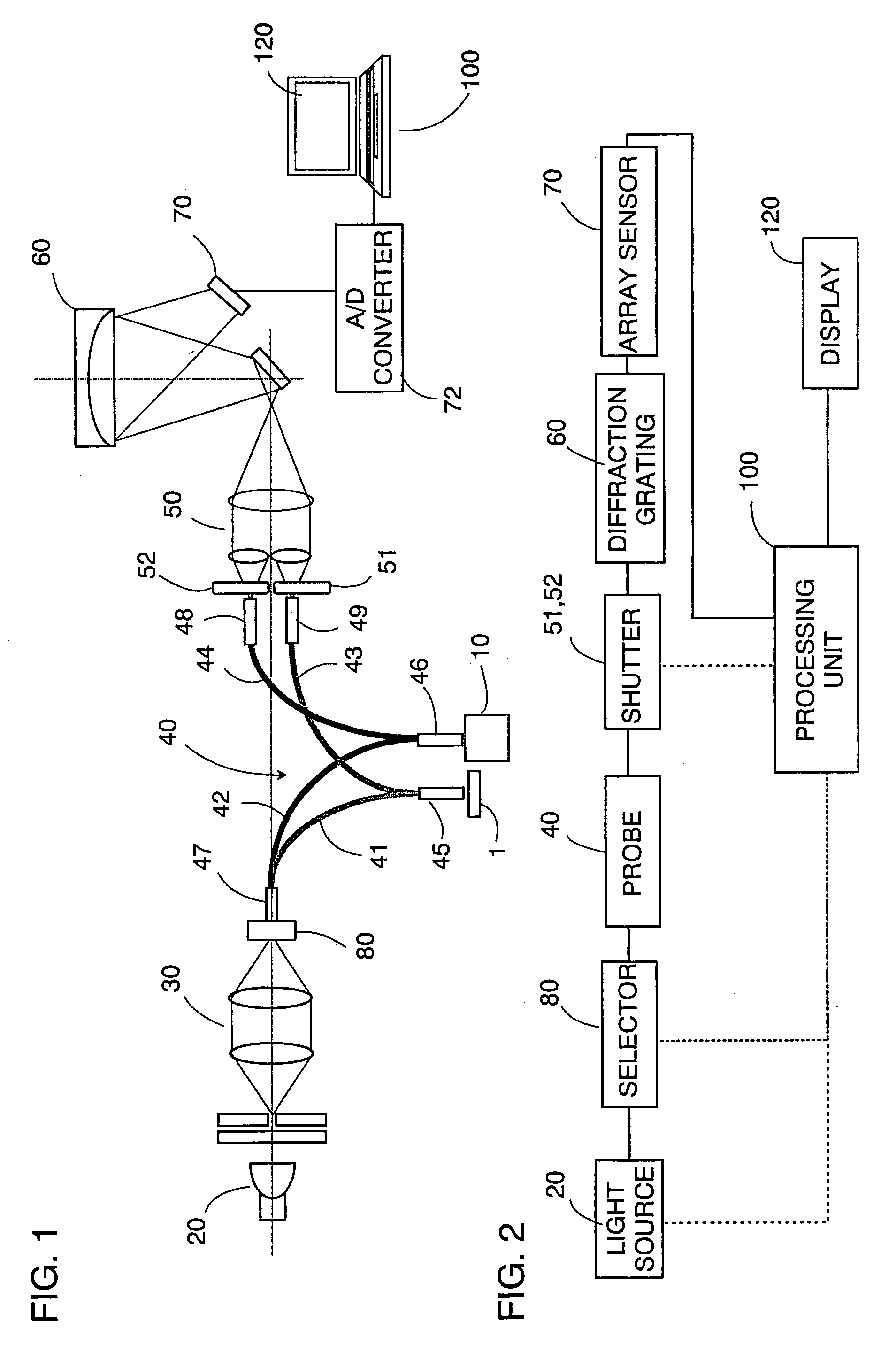
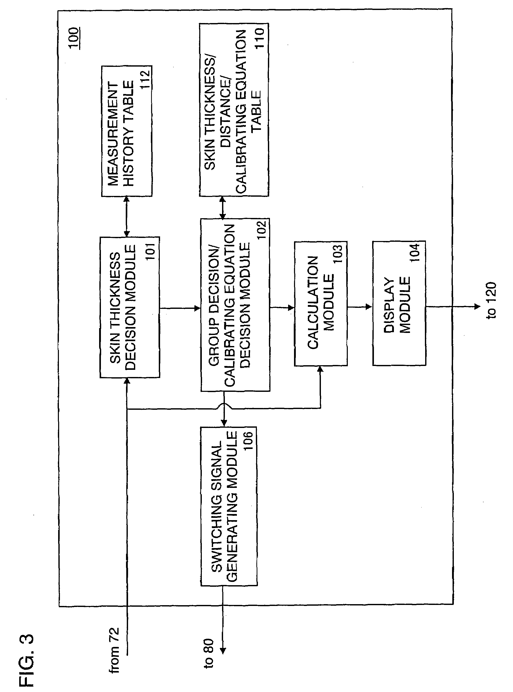
[0035]FIG. 1 and FIG. 2 show a device for calculating a biological component density in accordance with the present invention. This device comprises a light source 20 which is a halogen lamp, a light projecting lens group 30 which condenses a light having a NIR spectrum from the light source 20, a probe 40 for irradiating the light which passed the light projecting lens group 30 to a standard board 1 and to a skin 10 of a subject and for receiving the light reflected diffusely therefrom, a condenser lens group 50 which condenses the light from the probe 40, a diffraction grating 60 for dispersing the NIR spectrum which passed the condenser lens group 50, an array sensor 70 for detecting the NIR spectrum dispersed by the diffraction grating 60, and a processing unit 100 which processes the electrical signal indicative of the NIR spectrum from the array sensor 70 thereby calculating the biological component density. In this embodiment, glucose density is calculated as an example of th...

second embodiment

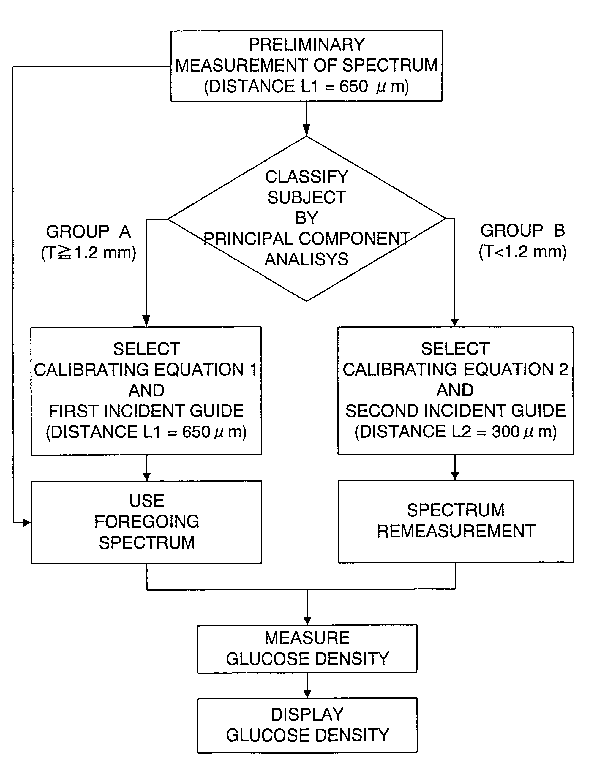
[0077]The present invention is not limited to the above embodiment, the distance between the incident guide and the reflective guide on the end face of the object head 46 may be fixed to 650 μm, as a second embodiment shown in FIGS. 17 and 18. In this embodiment, reliable measurements of the glucose density is also possible by the same procedure as the above embodiment, i.e., first, the skin thickness of the subject is measured by the principal component analysis of the reflective spectrum from the skin, which is also used for the measurement of the glucose density, and the calibrating equation in match with the group corresponding to the skin thickness is selected.

third embodiment

[0078]FIG. 19 shows the present invention, in which, the skin thickness is determined by using a ratio of an absorption coefficient of the NIR spectrum reflected from the skin of the subject at a wavelength of 1728 μm (Ab1728) to an absorption coefficient at a wavelength of 1670 μm (Ab1670), in order to select the group classified in terms of the skin thickness. That is, when “Ab1728 / Ab1670>α(α: constant)”, then the skin thickness is judged to be less than 1.2 mm, and when “Ab1728 / Ab1670≦α”, then the skin thickness is judged to be 1.2 mm or more. After that, like the above embodiment, the glucose density is measured by substituting the NIR spectrum data into the calibrating equation in match with the selected group. In this embodiment, the probe of which distance between the incident guide and the reflective guide is 650 μm is used.

[0079]In this way, the group can be selected based on the skin thickness using the unique absorption wave length of the NIR spectrum caused by the fat co...


PUM


Abstract

A method for calculating a biological component density of this invention comprises steps of irradiating a light of NIR spectrum to a skin of a subject, receiving the light of NIR reflected from the skin to obtain NIR spectrum data thereof, and substituting the NIR spectrum data into a predetermined calibrating equation to obtain a biological component density of the subject such as glucose density. This invention is characterized by preparing a plurality of the calibrating equations which are different from each other and are specific to each of plural groups which are classified in terms of a skin thickness parameter indicative of a skin thickness with respect to individuals of a species to which the subject belongs, determining the skin thickness parameter of the subject with a non-invasive technique and identifying the group of the subject in accordance with the determined skin thickness parameter, and deriving one of the calibrating equations in match with the identified group in order to calculate the biological component density of the subject.

Description

TECHNICAL FIELD[0001]The present invention relates to a method and a device for calculating a biological component density of a subject and, more particularly, it relates to a method and a device for calculating a biological component density for calculating a chemical component in body tissue by spectrochemical analysis using absorption of light in near-infrared region. Specifically, it relates to a useful method and a device to calculate glucose density in skin structure based on quantitative analysis.BACKGROUND ART[0002]Japanese Non-examined Patent Publication No.2000-131322 discloses a quantitative method of glucose density and a device for the method. This prior art comprises the steps of irradiating light of near infrared (hereinafter called NIR) spectrum to a skin of a subject, receiving the light of NIR reflected from the skin to obtain NIR spectrum data thereof, and substituting the NIR spectrum data into a predetermined calibrating equation to obtain glucose density of the...

Claims


Application Information

Patent Timeline
IPC IPC(8): A61B5/00A61B5/107A61B5/145A61B5/1455G01N21/35G01N21/359
CPCA61B5/14532A61B5/1455A61B5/1495A61B5/7264A61B5/1075A61B2562/0242G16H50/20
Inventor MARUO, KATSUHIKOTSURUGI, MITSUHIRO
Owner PHC HLDG CORP
Why Eureka
Try Eureka