Solenoid isolation valve

a solenoid and isolation valve technology, applied in the field of fuel systems, can solve the problems of not being easily determined, unable to build up pressure in the back side, and current electrically operated pilot-type, and achieve the effect of reducing the flow of gas

Inactive Publication Date: 2008-02-26
WANG WEI CHING +2
View PDF6 Cites 10 Cited by
  • Summary
  • Abstract
  • Description
  • Claims
  • Application Information

AI Technical Summary

Benefits of technology

[0005]Accordingly, it is an object of the present invention to provide a solenoid isolation valve of the above mentioned general type which avoids the disadvantages of the prior art.
[0006]It is also an object of the present invention to provide a solenoid isolation valve that will virtually open instantaneously, by introducing two special matching and contacting surfaces on the movable seal piston and the primary piston chamber to restrain gas flow communicating with gas inlet when the pilot piston starts to open.
[0007]It is also an object of the present invention to avoid the difficulty in determining the ratio of gas flow in and out of the chambers proximate the pilot piston for opening and closing the valve.
[0010]When the gas fills into the empty valve, the seal piston moves up slightly to allow gas flow into the chambers of valve, providing an equalization of pressures in chambers and sealing the valve and spring force resumes the seal piston to a closed position. When the solenoid is energized, pilot piston is moved to open the bleed orifice. The seal piston restrains the gas flow to decrease the gas pressure in the chambers, so that an instant opening of the valve to a wide-open position is ensured. While the valve is opened, the bleed orifice drains gas faster than in-flow in via the channel hole provided in the flange, to maintain the same pressure difference, so that the valve stays open. When the solenoid is de-energized, as the pilot piston adjusts itself to close the bleed orifice, there will be enough supply of gas via the channel hole to build up the gas pressure to close the valve.

Problems solved by technology

There exist some problems in the current electrically operated pilot-type, “instant-on” solenoid valves, especially during the opening and closing stage of the valve.
However, in this case, such ratio is rather critical and it can not be easily determined.
Hence, the pressure won't be able to build up in the back side.
Under this circumstance, because the spring force can not overcome the pressure difference between the back side and the front side of the primary piston, the valve might not close eventually.

Method used


Image

  • Solenoid isolation valve
  • Solenoid isolation valve
  • Solenoid isolation valve

Examples


Embodiment Construction

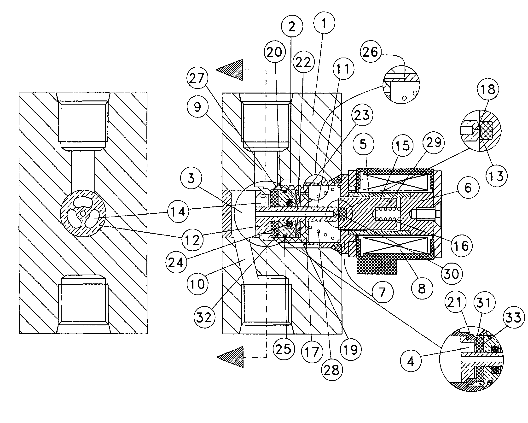
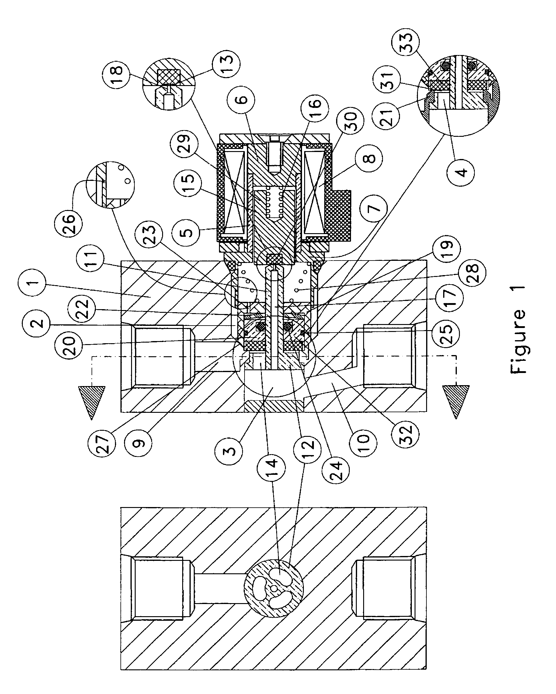
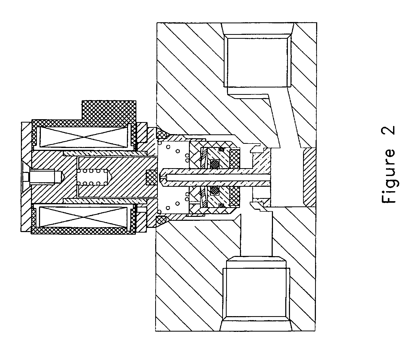
[0015]Attention is first directed to FIG. 1, which shows a solenoid isolation valve in section view. In housing 1, it provides the primary piston chamber 2 and the outlet chamber 3; both chambers are in gas communication with each other through the primary channel 4. The primary piston chamber 2 connects to the gas inlet 9. The outlet chamber 3 connects the gas outlet 10.

[0016]A non-magnetic tubular sleeve 5 with a magnetic closure 6 at one end connects to a magnetic hollow cylindrical flange 7. An electrical coil 8 around the tubular sleeve 5 for generating the magnetic field.

[0017]An axial center column 11 with a circular disk 12 at one end, and a bleed hole seat 13 at another end. There are vent holes 14 through the circular disk 12, parallel to the axis of the axial center column 11. The axial center column 11 mounts into the primary channel 4 with external threads on the circular disk 12. The column portion of the axial center column 11 sits in the primary piston chamber 2. The...


PUM


Abstract

An improved pilot-operated, “instant-on”, solenoid isolation valve discloses a new fluid passage route to save cost of drilling a longitudinal hole within the primary piston. Also, a new feature of primary piston assembly with a movable seal piston having a specific circumferential surface matching to valve body chamber to restrict fluid from front side into back side of the primary piston to produce pressure difference to induce instant valve open when solenoid is energized initially. It also introduces a channel hole in the flange of the sleeve assembly as a communication channel of supply of gas into the chambers of the back side of primary piston assembly. The diameter of the channel hole is not critical to determine in this new invent. As long as the size of the hole is smaller than that of the bleed hole, it can maintain pressure difference between the front side and back side of primary piston during valve opening operation. In addition, since the pilot piston and the primary piston assembly operate independently, the travel stroke of the primary piston assembly is unconstrained by the input electrical power.

Description

FIELD OF THE INVENTION[0001]The primary application field of the invention relates to fuel systems for compressed natural gas (CNG) vehicles or the like. It may be use for other applications, such as high pressure gas filling station.BACKGROUND OF THE INVENTION[0002]When compressed natural gas or compressed hydrogen gas is stored in cylinders at pressure as high as 6,000 psig, without equipped a fuel pump, an electrical solenoid is used to control fuel flow to quickly start and stop the fueling process. There exist some problems in the current electrically operated pilot-type, “instant-on” solenoid valves, especially during the opening and closing stage of the valve. In the prior arts U.S. Pat. No. 5,762,087 and No. 6,540,204; a ring segregates the primary piston to form a front side and a back side, where the front side is in the direction of the outlet. When the solenoid is energized, a pressure difference is created between the front side and the back side and it overcomes the bi...

Claims


Application Information

Patent Timeline
Patent Type & Authority Patents(United States)
IPC IPC(8): F16K31/12F02M59/36
CPCF02M59/366F02M63/0015F16K31/408
Inventor WANG, WEI-CHINGWANG, CHIA-PINGWANG, YU-CHING
Owner WANG WEI CHING
Why Eureka
Try Eureka