Network connector and connection system

a network connector and connection system technology, applied in the direction of power cables, cable connections, coupling devices, etc., can solve the problems of large time and effort, failure to transmit data, inadequate field made connections, etc., to improve signal performance of network components and facilitate coupling network components.

Inactive Publication Date: 2008-02-26
CARROLL JAMES A MR
View PDF10 Cites 50 Cited by
  • Summary
  • Abstract
  • Description
  • Claims
  • Application Information

AI Technical Summary

Benefits of technology

[0015]The connector system of the present invention solves many of the above discussed problems and generally includes a connector, connector cover, connector to RJ jack, a connector to connector jack and a RJ adapter. The connector system of the present invention is utilized to terminated twisted pair cables that are commonly routed within walls, ceilings and floors to be coupled the components of telephone and computer networks. The connector system of the present invention provides improved ease of coupling network components while at the same time providing improved signal performance for the network components by controlling cross talk that tends to occur between conductors of twisted pair cables when the twisted pairs are untwisted for coupling to the jacks that are used in currently available network systems.

Problems solved by technology

Problems are associated with installing jacks and plugs in the field related to inconsistency of method that occur from one installer to the next.
These result is failures in data transmission and the expenditure of large amounts of time and effort to troubleshoot and repair inadequate field made connections.

Method used


Image

  • Network connector and connection system
  • Network connector and connection system
  • Network connector and connection system

Examples


Embodiment Construction

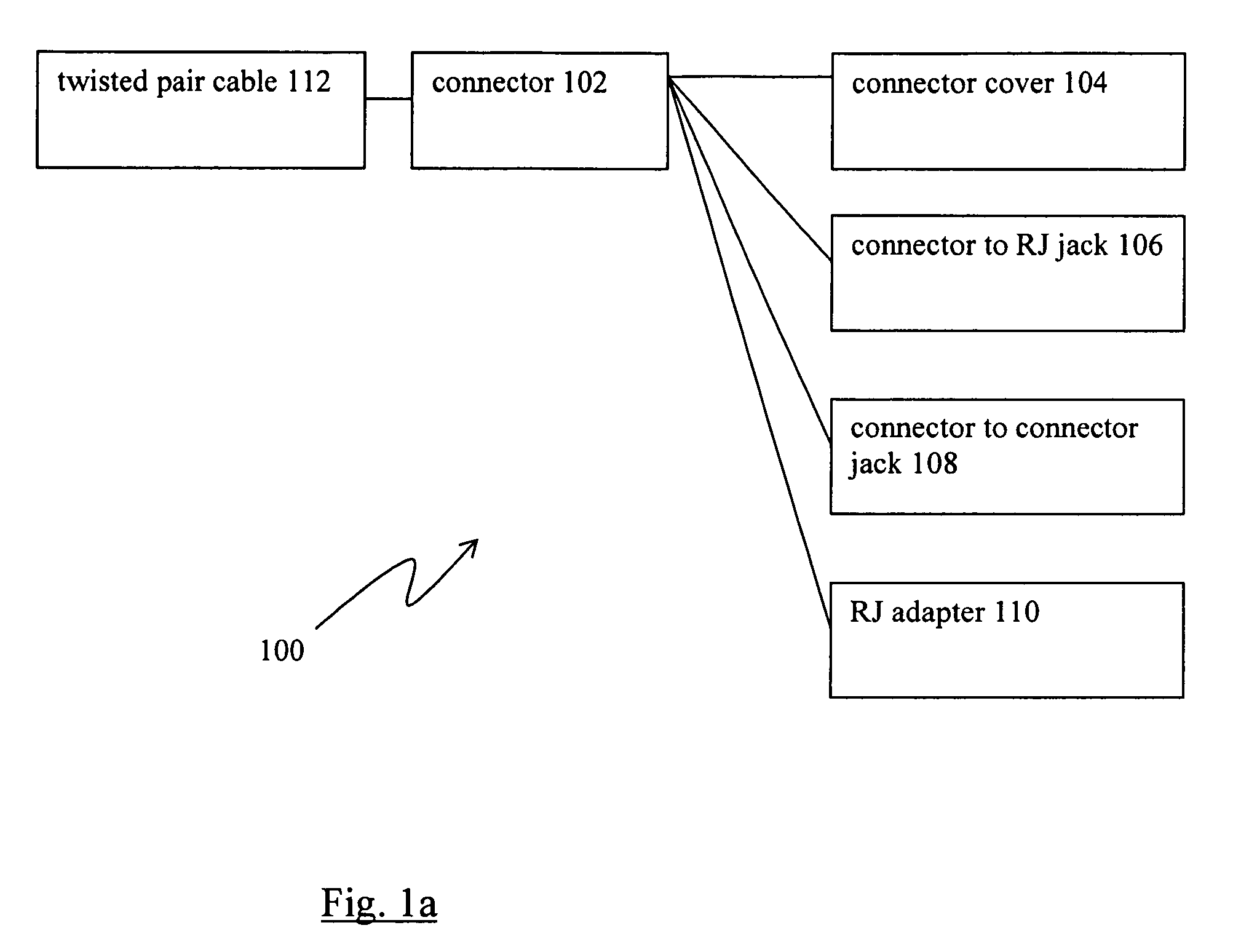
[0141]The network connector system 100 of the present invention, as depicted in FIG. 1a, generally includes connector 102, connector cover 104, connector to RJ jack 106, connector to connector jack 108 and RJ adapter.

[0142]Referring particularly to FIG. 1a, connector system 100 of the present invention generally includes connector 102, connector cover 104, connector to RJ jack 106, connector to connector jack 108 and RJ adapter 110.

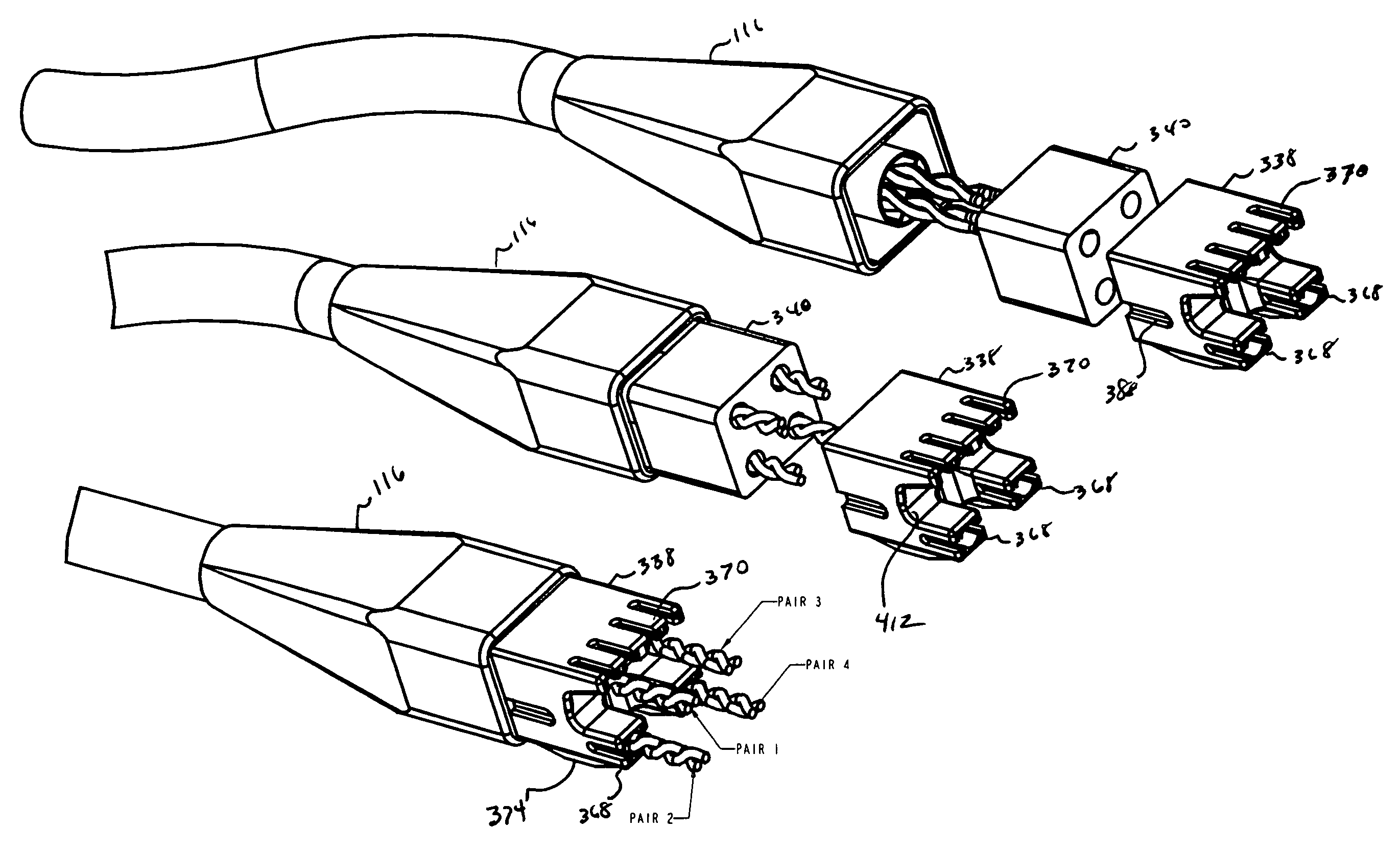
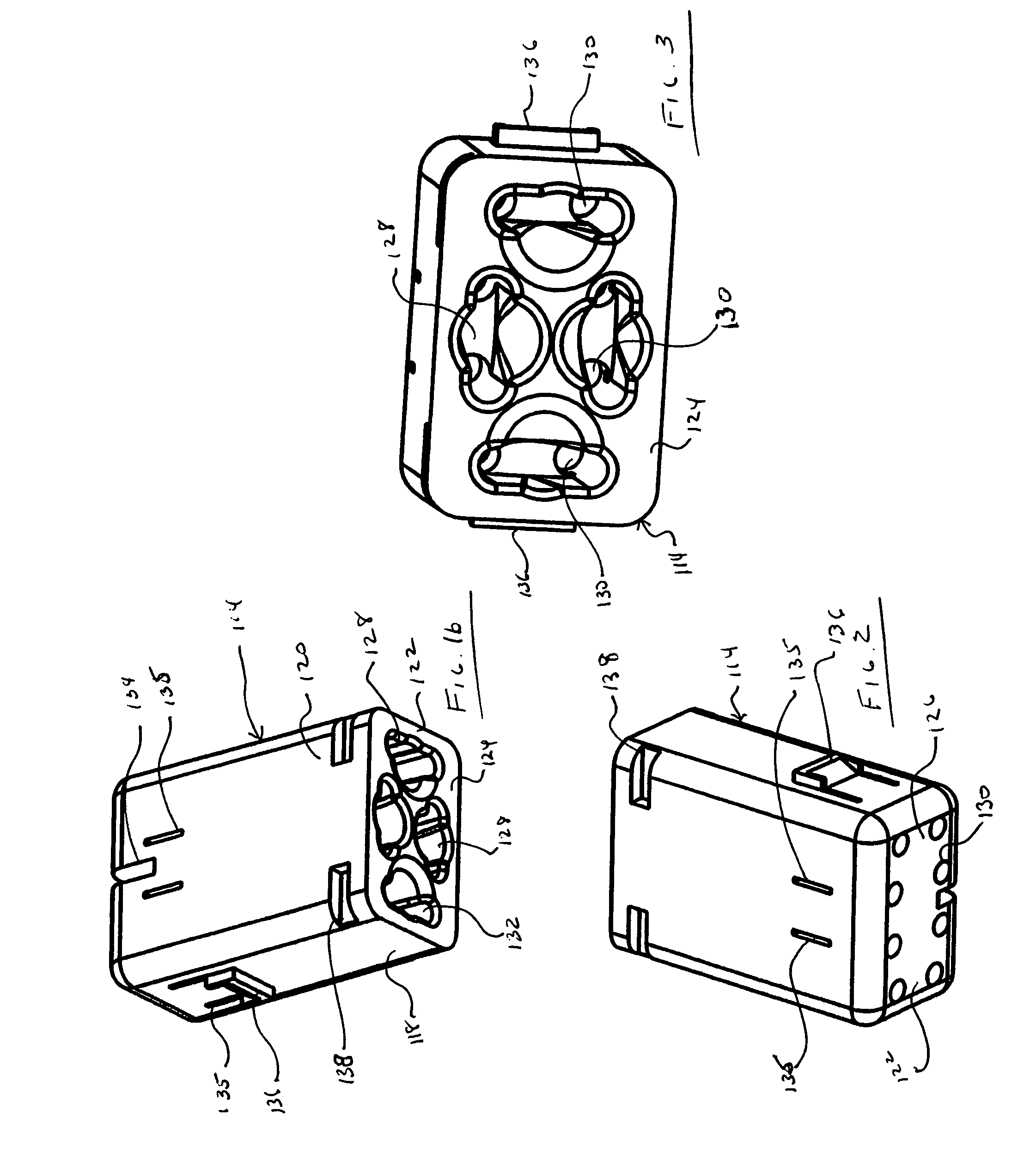
[0143]Referring to FIGS. 1b-13, connector 102 is adapted for connection to twisted pair of cable 112. Connector 102 generally includes pair separator 114 and strain relief 116.

[0144]In one aspect of the invention, pair separator 114 takes the form of a generally rectangular prism having smaller sides 118, larger sides 120 and ends 122. Ends 122 include first end 124 and second end 126. First end 124 defines channels 128. In one aspect of the inventions there are four channels 128. Second end 126 defines hole 130. In one aspect of the invention, there are ...


PUM


Abstract

A network connection system for connecting computer and telephone network components, including a twisted pair cable termination connector for use with twisted pair cable, the twisted pairs being arranged within an outer cable jacket such that each twisted pair substantially occupies a cross sectional quadrant of the cable. The connector includes a pair separator having four passages arranged to substantially keep the four twisted pairs in a quadrant relationship relative to one another and in which the twisted relationship of each twisted pair is maintained substantially until the conductors are electrically terminated to their respective conductive contact member; and a mating component adapted to couple with the twisted pair cable termination connector.

Description

CLAIM TO PRIORITY [0001]This application claims priority to U.S. Provisional Applications 60 / 751,199 filed Dec. 16, 2005 entitled “Network Connector and Connection System”, 60 / 831,649 filed Jul. 18, 2006 entitled “Network Connector and Connection System” and 60 / 837,494 filed Aug. 14, 2006 entitled “Network Connector and Connection System.” All of the above referenced Applications are incorporated in their entirety by reference.FIELD OF THE INVENTION [0002]The invention generally relates to connectors for wiring computer and telephone networks. More particularly, the invention relates to connectors for termination of twisted pair cables to network subcomponents.BACKGROUND OF THE INVENTION [0003]Twisted pair cables are commonly used for the wiring of computer and telephone networks. Twisted pair wire orientation is governed by EIA / TIA Standard 568B and industry connection methods.[0004]Conventional twisted pair cable includes four twisted pair conductors inside an outer insulation jac...

Claims


Application Information

Patent Timeline
Patent Type & Authority Patents(United States)
IPC IPC(8): H01R24/00
CPCH01R4/2429H01R9/035H01R13/508H01R31/06H01R13/6658Y10S439/941H01R24/64H01R13/65915
Inventor CARROLL, JAMES A.FINKE, THOMAS R.
Owner CARROLL JAMES A MR
Why Eureka
Try Eureka