Sludge treatment

a technology of sludge treatment and apparatus, applied in the direction of multi-stage water/sewage treatment, separation process, filtration separation, etc., can solve the problems of press/conveyor system, high friction, and none of the known solutions have given a satisfactory solution to the problem, so as to improve control, reduce handling, storage and disposal costs, and clean sludge

Active Publication Date: 2008-02-26
SULZER MANAGEMENT AG
View PDF41 Cites 21 Cited by
  • Summary
  • Abstract
  • Description
  • Claims
  • Application Information

AI Technical Summary

Benefits of technology

[0010]The object of the present invention is to provide an apparatus and a method that enable dewatering of sludge to a high degree of dryness in a press and transport of the dewatered sludge over considerable distances and at any inclination to the horizontal.
[0012]As a result, the apparatus of the invention enables operation of a screw press, piston press or wash press in a way that makes it possible to dewater the sludge to a high degree of dryness at the same time as the dewatered sludge can also be transported in tube conveyors with or without transport screws therein over considerable distances and at any inclination to the horizontal without problems. By using operational parameters in the press to control the flow of dewatered sludge out of the press and / or the compaction device, together with the breaking up or shredding of the lumps or “sausages” of dewatered sludge, a dewatered sludge having a high dryness as well as being easily transportable over long distances and at any angle of inclination in tube conveyors and / or screw conveyors is achieved.
[0026]The above mentioned transport screw of the tube conveyor may be designed so that at stand still there will be essentially no flow of sludge out of the press. By controlling the rate of rotation of such a transport screw any desirable flow combined with breaking up or shredding of the sludge lumps or “sausages” can be easily achieved.
[0027]The upstream end of the transport screw may be provided with a centrally attached conical tip that will break up the dewatered sludge and direct it to the part of the transport screw that provides the shredding as well as provide better control and further protect the conveyor screw from overloading.
[0028]In the case that the transport screw in the tube conveyor is used in the way described above it has three functions: a) it controls the flow of dewatered sludge out of the press according to the signal originating from the measurement of parameters in the press and / or provided by a timer or predetermined time sequence, b) it breaks up lumps and / or “sausages” of sludge and c) it transports away the pieces of sludge resulting from the shredding / break up. Using this method the sludge can be dewatered to a high dryness at the same time as transportation of the dewatered sludge over long distances and at any angle of inclination is possible by use of a tube conveyor with or without a transport screw therein. The dewatered sludge will further be discharged from the tube screw conveyor in a form which is ideal for handling and incineration.
[0029]The wash process in a wash press can also be improved so that a cleaner sludge can be produced using the present invention. Cleaner sludge means lower handling, storage and disposal costs for screenings from wastewater treatment. It also means cleaner cellulose pulp and improved recovery of chemicals when the invention is used in the pulp and paper industry, which has great economic value. Recovery of chemicals from sludge in the chemical industry is another application.

Problems solved by technology

However, current methods for obtaining a dry sludge after dewatering lead to problems in the press / conveyor system caused mainly by problems in the transportation of the sludge in the tube conveyors that are normally used in conjunction with the presses.
Since dry sludge is in the form of lumps, aggregates or a hard “sausage” it causes a high friction against the conveyor tube wall, so that it might get stuck in the conveyor and cause blocking of the same.
The problem of combining dewatering the sludge to a high dryness in presses and transporting the dewatered sludge in a tube conveyor or tube screw conveyor is well known in the industry and a number of solutions have been tried but none of the known solutions has given a satisfactory solution to the problem.
However it is in the nature of sludge and sludge dewatering that the properties of the sludge are variable and this will directly affect the dewatering performance of the press.
These tube sections would have to be changed in accordance with sludge properties, which would be impractical.
The solution using widening conveyor tubes will consequently produce sub-optimal results in respect of dryness of the sludge and it will also be susceptible to disturbances if an unforeseen change in the parameters should occur.
In this way a certain adjustment of the tube can be carried out during operation in case the sludge characteristic and dryness after dewatering should change, but this requires constant supervision or a complicated control system.
Changes cannot be made quickly enough to properly adjust to changes in load or sludge characteristics and the span of possible settings of the slope is limited.
A further drawback of this system is that it can only be used for transporting the sludge a short distance and it cannot be used for lifting the sludge more than a short distance to a conveyor and / or a container.
The reloading into a big diameter screw conveyor is costly and impractical.
The lay-out of wastewater treatment plants often requires closed transport of the sludge over long distances and also vertically between floors due to building constraints.

Method used


Image

  • Sludge treatment
  • Sludge treatment
  • Sludge treatment

Examples


Embodiment Construction

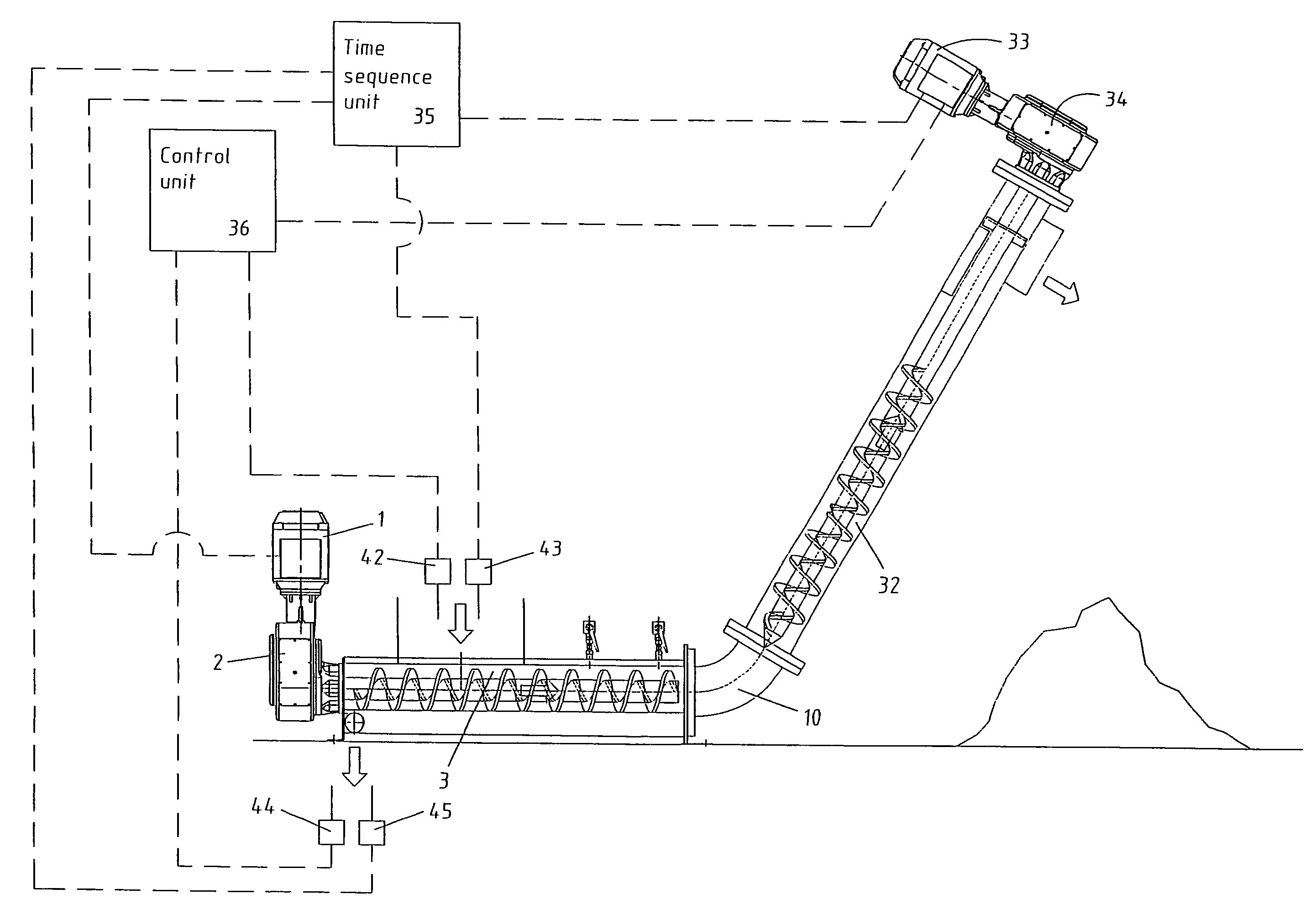
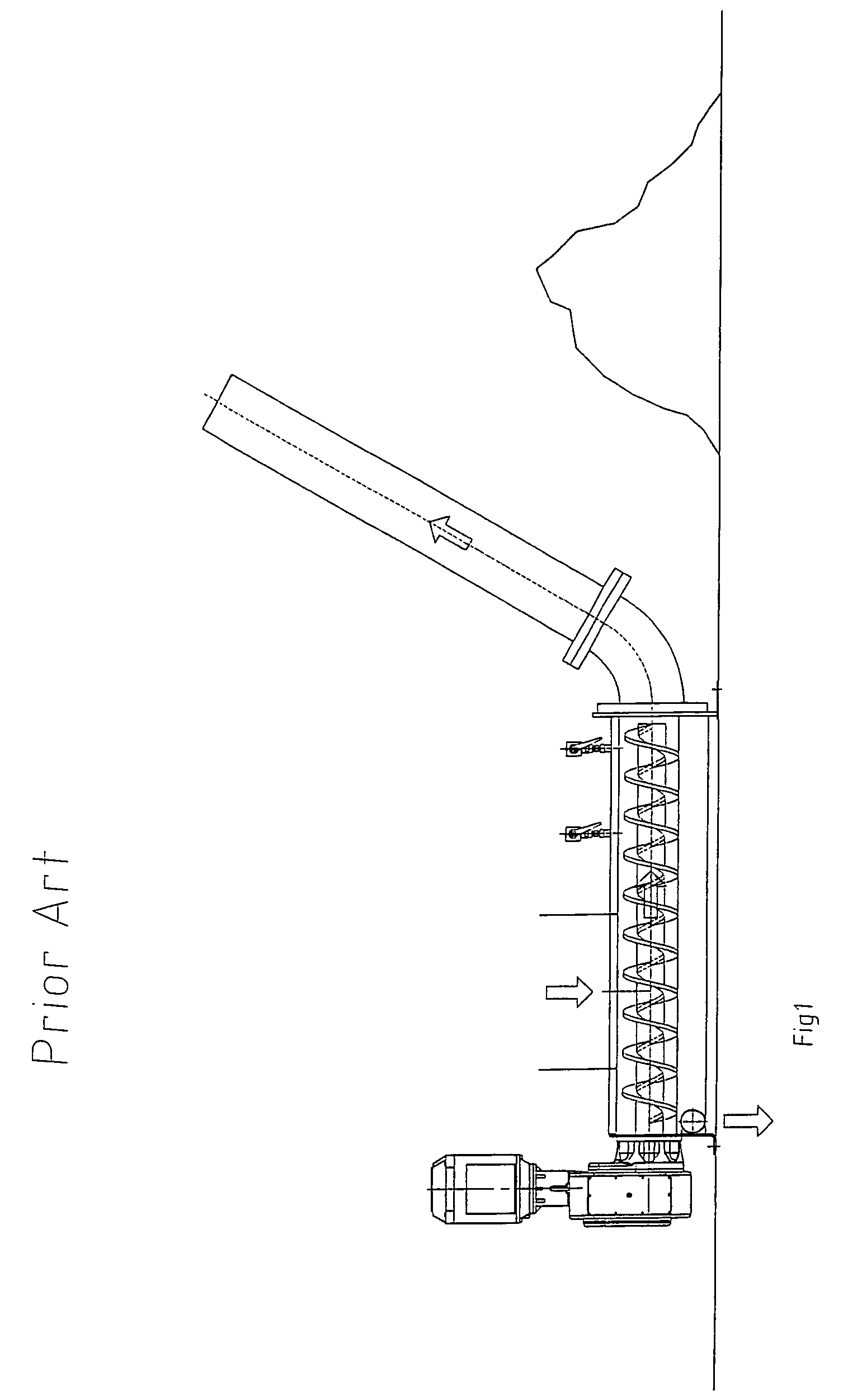
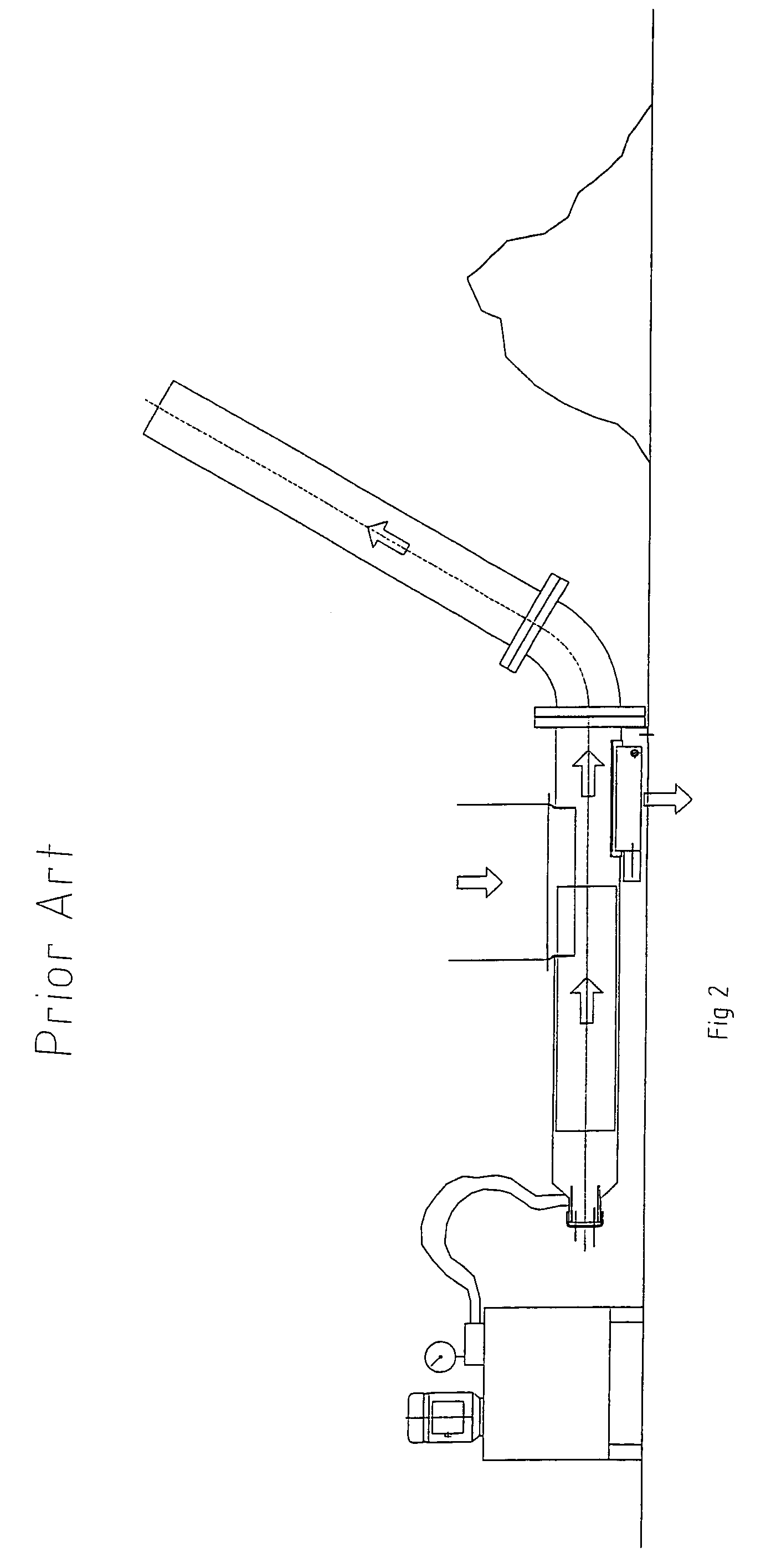
[0038]FIGS. 1, 2 and 3 show apparatuses according to prior art. Accordingly, FIG. 1 shows a conventional screw press / screw wash press for sludge dewatering including a compaction device and followed by a tube conveyor for transporting dewatered sludge. FIG. 2 shows a conventional piston press for sludge dewatering including a compaction device and followed by a tube conveyor. FIG. 3 shows a modified conventional screw press / screw wash press for sludge dewatering including a compaction device and followed by a tube conveyor for transporting dewatered sludge having a conveying tube with widening diameter in the direction of transport in order to avoid blocking by dry sludge.

[0039]Embodiments of the present invention will now be explained in detail with reference to FIGS. 4 to 11.

[0040]FIG. 4 shows a general embodiment including a screw press 3, a compaction device 10 in the form of a tube bend connected to the screw press 3 downstream thereof and a tube conveyor 11 extending upwardly ...


PUM

PropertyMeasurementUnit
timeaaaaaaaaaa
flow rateaaaaaaaaaa
pressureaaaaaaaaaa

Abstract

An apparatus for treating sludge, comprises a press for dewatering the sludge, a compaction device for receiving and compacting sludge dewatered by the press, a shredder for receiving and shredding sludge compacted by the compaction device, and a tube conveyor for conveying shredded sludge from the shredder. The press is controlled to vary the flow rate of the sludge in response to at least one sensed operational parameter of the press, such as the momentary power for operating the press, pressure in the sludge in the press, sludge concentration in the press, sludge feed flow to the press or separated water flow from the press.

Description

FIELD OF THE INVENTION[0001]The present invention relates to an apparatus and method for treating sludge. More particularly, the invention relates to dewatering of sludge and transport of the dewatered sludge.BACKGROUND OF THE INVENTION[0002]Processes for treatment of polluted water normally involve a screening step, in which solids are removed by passage of the water through a screen. The removed solids, the screenings, form a wet, water-containing sludge that has to be dewatered and in many cases washed before the it can be deposited, incinerated or taken care of in another way. In order to obtain a manageable sludge that can easily be transported, deposited or incinerated it is essential that the solids content of the dewatered screenings is as high as possible. The same type of dewatering, and / or solids / liquid separation, and the same type of problems as those described below are also encountered in many industrial processes e.g. the dewatering and washing of cellulose pulp in t...

Claims


Application Information

Patent Timeline
Patent Type & Authority Patents(United States)
IPC IPC(8): C02F11/12B30B9/12B30B9/16
CPCB30B9/121B30B9/163B30B9/128B30B9/125
Inventor CHRISTOPHERSSON, JESPER
Owner SULZER MANAGEMENT AG
Why Eureka
Try Eureka