Method for producing microparticles loaded with proteins

a technology of proteins and microparticles, applied in the field of protein-loaded microparticles, can solve the problems of low loading densities and/or very variables, poor spatial accessibility of functional groups, and high degree of lot to lot variability, and achieve low bleeding, good storage stability, and high binding capacity

Inactive Publication Date: 2008-02-26
ROCHE DIAGNOSTICS OPERATIONS INC
View PDF13 Cites 562 Cited by
  • Summary
  • Abstract
  • Description
  • Claims
  • Application Information

AI Technical Summary

Benefits of technology

[0015]Hence the object of the present invention was to provide a method which allows the manufacture of adsorptively loaded microparticles on an industrial scale. Furthermore the invention also intends to provide protein-loaded microparticles that can be obtained by loading under strongly alkaline conditions and have a high binding capacity while at the same time having a low degree of bleeding and a good storage stability. The invention also encompasses advantageous applications of the microparticles coated under alkaline conditions in immunological detection systems.

Problems solved by technology

However, the initial particles used for covalent coating methods exhibit a high degree of lot to lot variability with regard to the density of functional groups, and the functional groups on the surface have a low storage stability which results in low loading densities and / or very variable results after loading.
Another disadvantage of covalent coating methods is that the spatial accessibility of the functional groups is often poor.
For this reason the loading densities required for an application, e.g., in a sensitive immunoassay, are often not achieved with particles coated in this manner.
Covalent chemical coupling can also result in an inactivation of the coated protein.
In such a multilayer method a delayed bleeding can occur due to delayed desorption.
This increased bleeding is due to the fact that the adsorptive coating occurs by means of relatively weak ionic and van der Waals interactions.
An additional disadvantage of the methods known from the prior art is the strong tendency of the hydrophobic particles to aggregate.
The basic hydrophobic structure of the particles results in an increased tendency of these particles to form aggregates with one another which has a disadvantageous effect on the measurement accuracy in subsequent methods of determination using these particles.
Furthermore these particles also have an increased tendency to unspecifically bind sample components when used in immunological tests due to their hydrophobic properties.
Unspecific binding in such test systems is well-known to have a negative effect on test characteristics such as the signal-to-noise-ratio, or it can lead to false-positive and also to false-negative results.
The centrifugation or sedimentation has the effect that the loaded particles come very close to one another and in an unfavorable case form aggregates.

Method used


Image

  • Method for producing microparticles loaded with proteins
  • Method for producing microparticles loaded with proteins
  • Method for producing microparticles loaded with proteins

Examples


specific embodiments

Example 1

Bead Coating

1.1 Reference Beads

[0048]DYNAL M-280 beads were coated as described in DE 19924643.

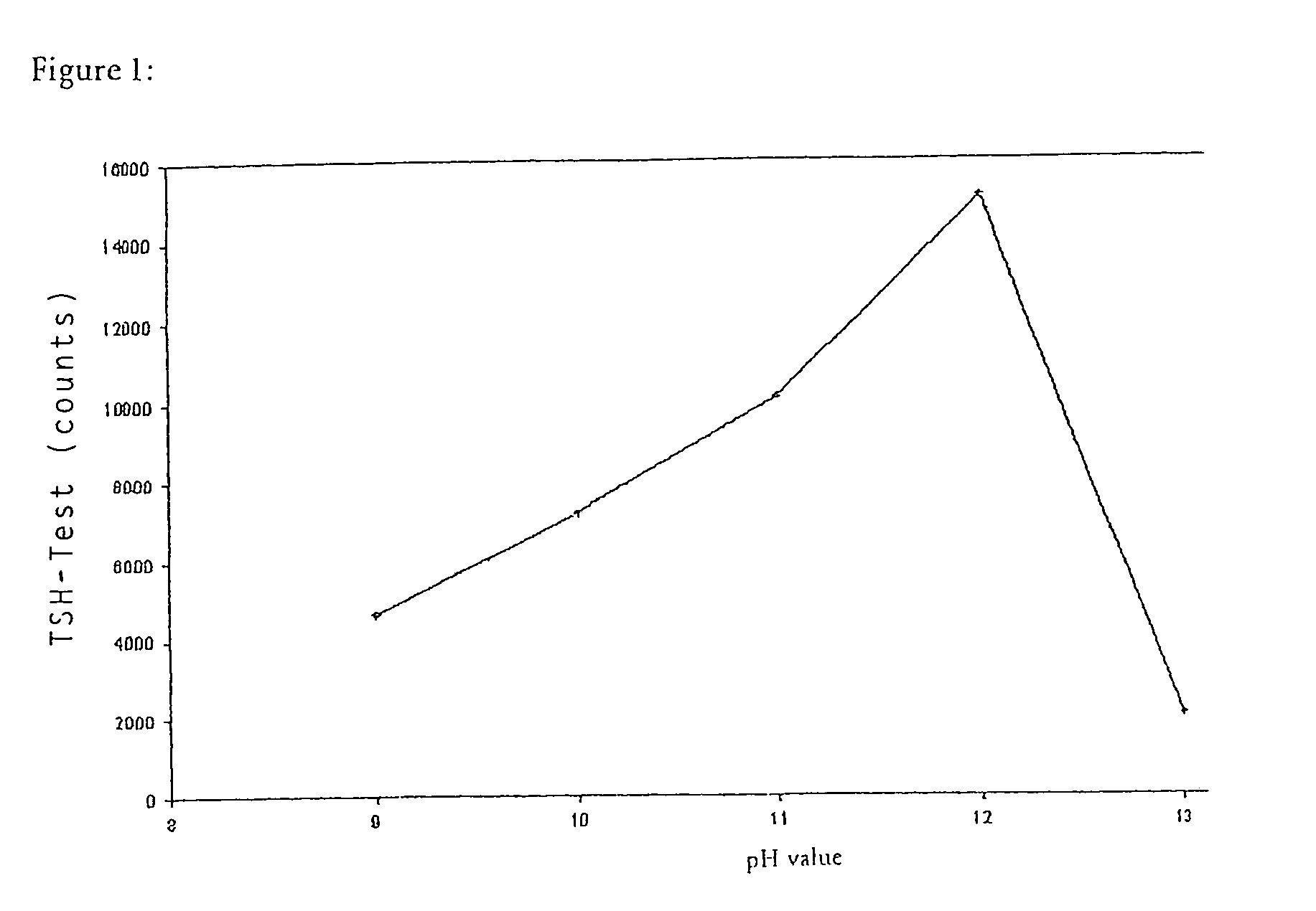
1.2 Alkaline Coating (pH Optimization)

[0049]50 mg magnetic beads (DYNAL M-270 or DYNAL M-280) were washed successively, first with isopropanol, then several times with 5 ml portions of 50 mM Na phosphate buffer (pH 9.0). Subsequently the beads were resuspended in 4 ml 50 mM Na phosphate buffer (pH 9.0). Afterwards 10 mg polymerized streptavidin (poly-SA) dissolved in 1 ml 50 mM Na phosphate buffer pH 6.3 was added. The pH was then adjusted to the desired value between pH 10.0 and pH 12.5 with NaOH. The preparation was incubated for 72 hours on a roller mixer. Subsequently the beads were washed alternately with 40 mM Na phosphate buffer (pH 7.4) and 1 percent TWEEN 20 (ICI Americas Inc.) solution (in the same basic buffer). The beads were subsequently incubated and washed several times with a solution consisting of sodium phosphate buffer (10 mM Na phosphate 0.15 M NaCl, pH 7.4) an...

example 2

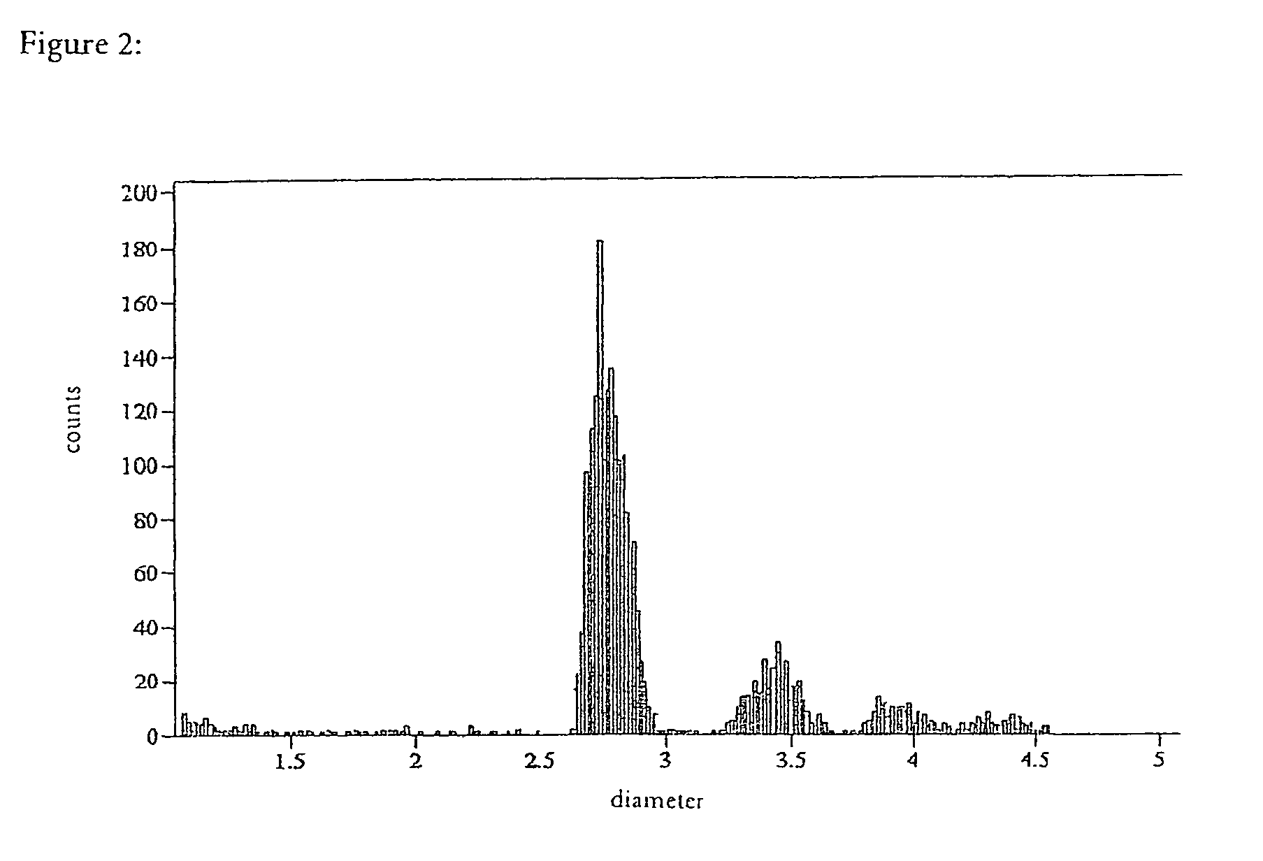
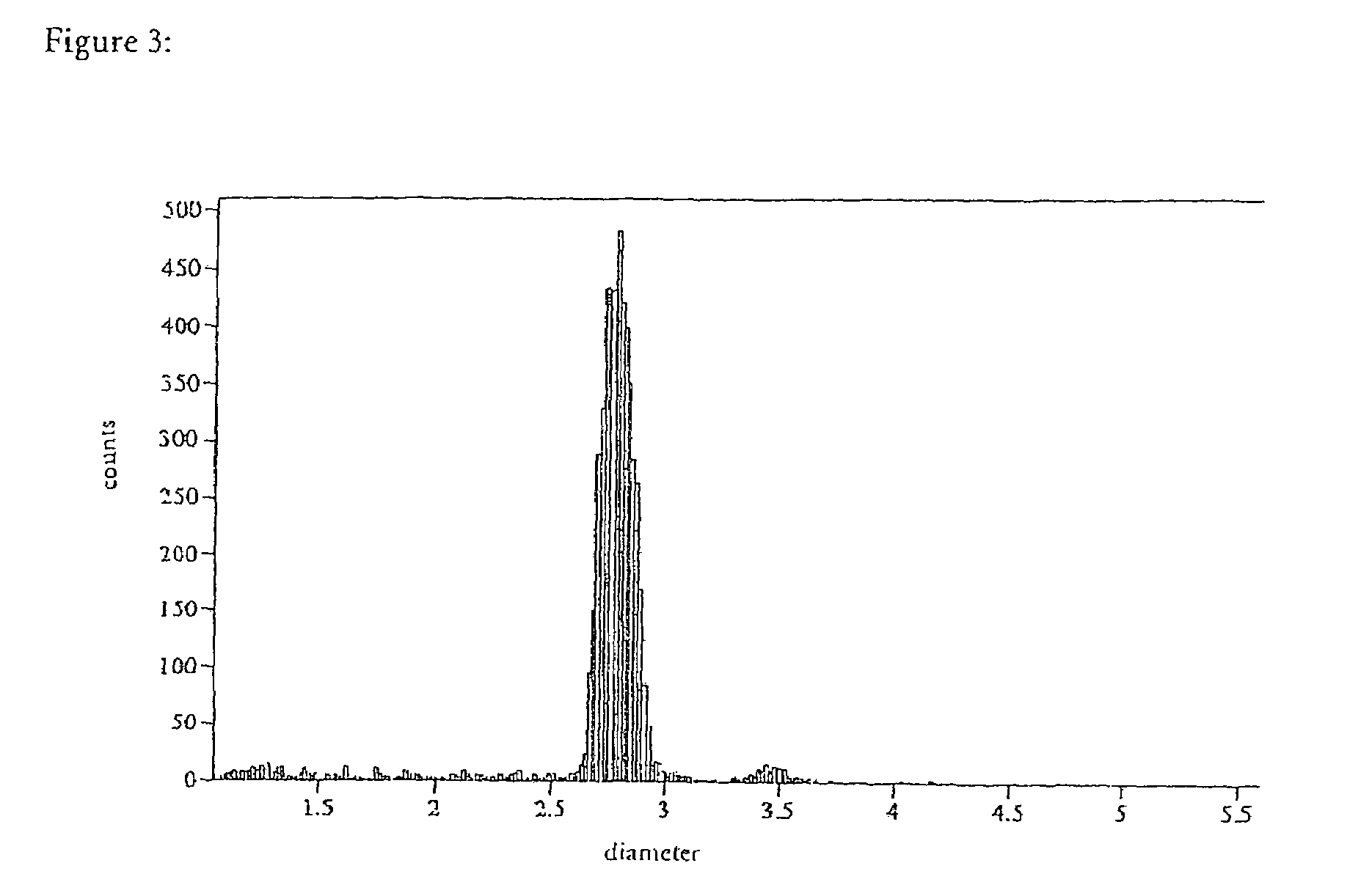
Particle Distribution

[0051]The DYNAL M-280 and M-270 beads coated by the method described above were compared with M-280 beads coated by a conventional method using a particle counter (Coulter Multisizer II, FIGS. 2-4). In the case of the alkaline coating the result was a considerably more homogeneous distribution of the coated beads with substantially lower proportions of dimeric, trimeric, and higher aggregates. This is shown by comparing FIGS. 3 and 4 with FIG. 2.

example 3

Bleeding Properties

[0052]The bleeding of coated proteins occurs very slowly under normal storage conditions (4-8° C.) over many months. In order to simulate bleeding under storage conditions, a short-term model was used. For this the coated particles were stored for 21 days at 35° C. on a roller mixer. The biotin binding capacity of the supernatant which is due to streptavidin that has bled off is determined, for example, using radioactively labelled biotin.

[0053]The bleeding tendency is stated in ng as SA / mg particles. In order to determine the bleeding, a standard curve is established using monomeric streptavidin, and the biotin binding capacity of the supernatant of stressed microparticle suspensions is read off from this curve. In the case of the microparticles coated according to Example 1, the bleeding tendencies were surprisingly low and were regularly below 150 ng / mg, and in most cases even less than 100 ng / mg after stress.


PUM

PropertyMeasurementUnit
sizeaaaaaaaaaa
sizeaaaaaaaaaa
pHaaaaaaaaaa

Abstract

The present invention concerns a method for producing microparticles loaded with proteins which is characterized in that the microparticles are loaded in suspension under strongly alkaline conditions. The invention also concerns microparticles which can be produced using this method and their use in a binding test e.g. in an immunoassay.

Description

RELATED APPLICATIONS[0001]This application is a continuation of international application PCT / EP02 / 08789 filed Aug. 7, 2002 and claims priority to European application EP 01118812.5 filed Aug. 10, 2001.FIELD OF THE INVENTION[0002]The present invention concerns a method for producing microparticles loaded with proteins which is characterized in that the microparticles are loaded in suspension under strongly alkaline conditions. The invention also concerns microparticles which can be produced by this method and their use in a binding test, e.g., in an immunoassay.BACKGROUND OF THE INVENTION[0003]Microparticles loaded with proteins are known and are often used as a solid phase in medical, immunological, and diagnostic test procedures. The unloaded initial particles (also referred to as beads) are mainly composed of latex, e.g., polystyrene latex, and can often be magnetized due to a content of magnetite or a core made of magnetite. Proteins are usually coupled to the latex particles in...

Claims


Application Information

Patent Timeline
Patent Type & Authority Patents(United States)
IPC IPC(8): B05D7/00G01N33/546G01N33/553A61K9/14A61K9/16G01N33/48G01N33/53G01N33/543G01N33/545
CPCA61K9/1676G01N33/54326G01N33/54353G01N33/545
Inventor FINKE, ANDREASKLAUSE, URSULADONIE, FEDERICHERRMANN, RUPERTVON DER ELTZ, HERBERTSLUKA, PETERJONA, WOLFGANG
Owner ROCHE DIAGNOSTICS OPERATIONS INC
Why Eureka
Try Eureka