
Gravity extraction air launch system for launch vehicle

a launch system and gravity extraction technology, applied in the direction of launching weapons, launching/towing gear, transportation and packaging, etc., can solve the problems of reducing the structural weight of the propellant tank, limiting the launch range, and reducing the cost of using the national range in the united states. , to achieve the effect of minimizing hardware and reducing the loss of forward velocity

Active Publication Date: 2008-03-04
SARIGUL KLIJN MARTINUS M +1
View PDF12 Cites 12 Cited by
  • Summary
  • Abstract
  • Description
  • Claims
  • Application Information

AI Technical Summary

Benefits of technology

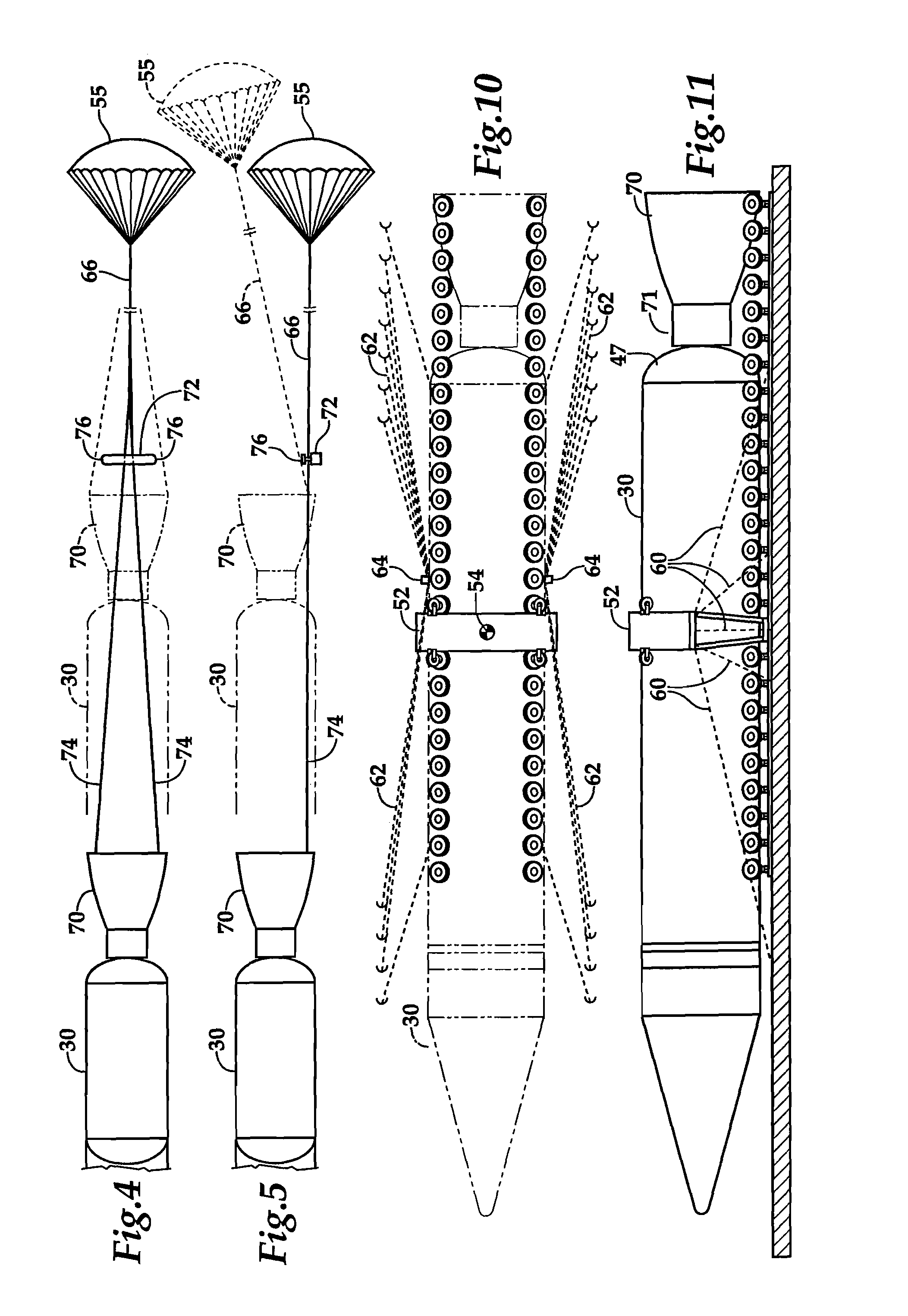
[0007]To minimize the load on any single tire pair, a greater number of tires are arranged at the end of the track formed by the pairs of tires where the vehicle tips as it exits the carrier aircraft. The last three tire groups utilize four tires arranged circumferentially with pairs of tires on each sides of the launch vehicle. The four tires making up the first group of the last three tire groups tires are arranged slightly above of the level of the groups of all the previously transited groups of two opposed tires which ride against the outer circumference of the launch vehicle. The four tires making up the second to last tire group are arranged above the level of the previously transited groups of two opposed tires and lower than the tires in the first group of the last three tires groups. The four tires making up the last group of tires are arranged below the level of the previously transited groups of two opposed tires. By adjusting the relative height of the last three groups it is possible to reduce the maximum load on any one group of tires.
[0008]It is an object of the present invention to provide a method of air launching a launch vehicle which maximizes the payload performance of the dropped vehicle.
[0009]It is a further object of the present invention to provide a method of launching a launch vehicle which minimizes the amount of equipment which falls away from the launch vehicle.
[0011]It is another object of the present invention to provide an apparatus for limiting the line load applied to the loading ramp of a carrier aircraft as a launch vehicle exits the aircraft.
[0012]It is yet another object of the present invention to provide an apparatus and method for bringing the launch vehicle to a near vertical orientation while minimizing hardware and loss of forward velocity.

Problems solved by technology

At a typical rocket range, launches will be limited with respect to the launch azimuth which can be flown by the necessity of avoiding overflight of densely populated areas.
For low-cost launch systems, the cost of using a national range in the United States can exceed 30 percent of total costs associated with a particular launch.
The limitations associated with fixed ranges have caused at least one supplier of launch services to fly vehicle launches from a floating ocean platform, and another supplier of launch services to use a carrier aircraft where the launch vehicle is attached beneath the carrier aircraft or beneath the carrier wing.
Reduced atmospheric pressure also allows the use of a lower engine chamber pressure, which, particularly in the case of a pressure fed vehicle, can result in substantially decreased structural weight for the propellant tanks.
This known approach has several disadvantages including high loadings caused by the substantial extraction loads, and the need to expend or recover the extraction cradle.
Furthermore, the extraction parachutes, followed by orientation parachutes, substantially eliminate the forward velocity of the launch vehicle, thus limiting the benefit which is gained from the air launch.

Method used


Image

  • Gravity extraction air launch system for launch vehicle
  • Gravity extraction air launch system for launch vehicle
  • Gravity extraction air launch system for launch vehicle

Examples


Embodiment Construction

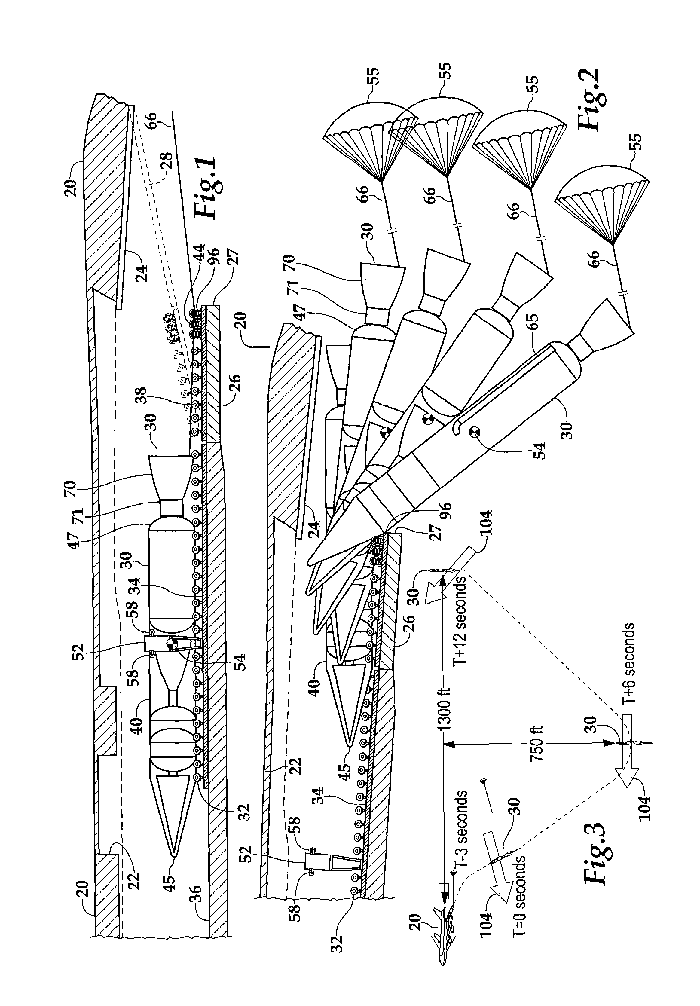
[0026]Referring more particularly to FIGS. 1-11, wherein like numbers refer to similar parts, a carrier aircraft 20, for example a C-17, is shown in FIGS. 1 and 2. The carrier aircraft 20 has an internal cargo bay 22, which opens to the rear 24 of the aircraft so that cargo can be air dropped. The cargo bay 22 has a loading ramp 26 with an end 27 over which air cargo is dropped. The loading ramp 26 can function as one half of the rearwardly facing cargo door 28 as shown in FIG. 1. A launch vehicle 30 rests on a carrier and drop system 32 which has two parts, a carrier part 34, which mounts to the cargo deck 36 within the cargo bay 22, and a vehicle drop portion 38 which includes three final banks of rolls 44 which make up a teeter section. The drop portion 38 is mounted to the loading ramp 26.

[0027]As shown in FIG. 6, the carrier and drop system 32 supports the external cylindrical shell 40 of the launch vehicle 30 on pairs of pneumatic tires 42. As shown in FIG. 1, the launch vehic...


PUM


Abstract

A launch vehicle is deployed from an aircraft using gravity extraction of the launch vehicle with the aid of a small parachute which assists the extraction and damps the yaw and pitch of the launch vehicle. The launch vehicle is supported on two rows of tires which are rotatably mounted to the aircraft. Gravity and the drag force of the parachute causes the launch vehicle to roll on the tires along the load deck and out of the aircraft. Because the extraction forces are dominated by gravity, the launch vehicle acquires a rotation in the pitch axis as the launch vehicle leaves the aircraft. After the launch vehicle clears the aircraft, the launch vehicle rotates in the pitch plane, and is damped in the pitch plane by the parachute to a pitch attitude which is 70-80° and the vehicle engine is ignited, detaching the drag parachute.

Description

STATEMENT AS TO RIGHTS TO INVENTIONS MADE UNDER FEDERALLY SPONSORED RESEARCH AND DEVELOPMENT[0001]This invention was made with Government support under Agreement No. HR0011-04-9-4072 awarded by DARPA. The Government has certain rights in the invention.BACKGROUND OF THE INVENTION[0002]Many designs have been considered for launching an orbital launch vehicle from a carrier aircraft. The designs which have been considered include carrying the launch vehicle on top of the carrier aircraft, on the bottom of the aircraft, under the aircraft wing, towing the launch vehicle behind the aircraft, and carrying the launch vehicle within the cargo area inside the aircraft. Launching a launch vehicle from a carrier aircraft, while having some limitations in terms of maximum gross weight of the launch vehicle, has many operational advantages. Launching from a carrier aircraft avoids the costs and limitations associated with ground-based launch ranges. Ranges may have restrictions limiting the numb...

Claims


Application Information

Patent Timeline
IPC IPC(8): B64D1/12B64F1/04
CPCB64D1/04F41F3/06F41F5/00
Inventor SARIGUL-KLIJN, MARTINUS M.SARIGUL-KLIJN, NESRIN
Owner SARIGUL KLIJN MARTINUS M
Learn More