
X-ray tube cathode overvoltage transient supression apparatus

a cathode and overvoltage transient technology, applied in the field of x-ray and computed tomography systems, can solve the problems of filament insulation breakdown from spit activity, x-ray system becoming inoperative, minor insulation on leads and cathode cable terminals, etc., to prevent overvoltage transients and prevent the occurrence of overvoltage transients

Active Publication Date: 2008-03-04
GE MEDICAL SYST GLOBAL TECH CO LLC
View PDF20 Cites 2 Cited by
  • Summary
  • Abstract
  • Description
  • Claims
  • Application Information

AI Technical Summary

Benefits of technology

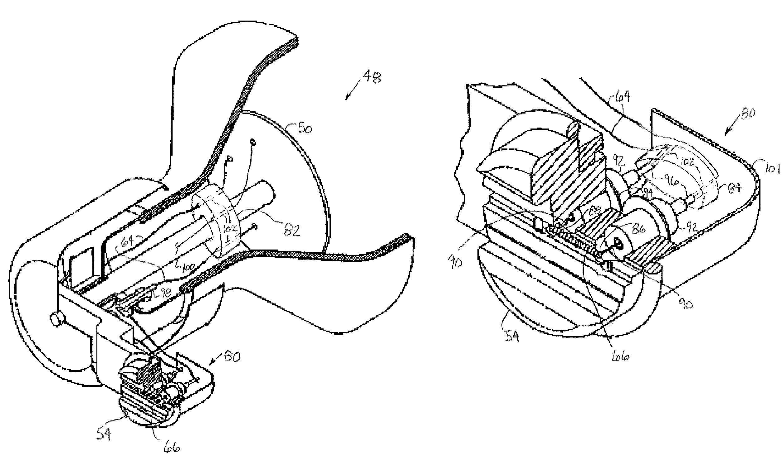
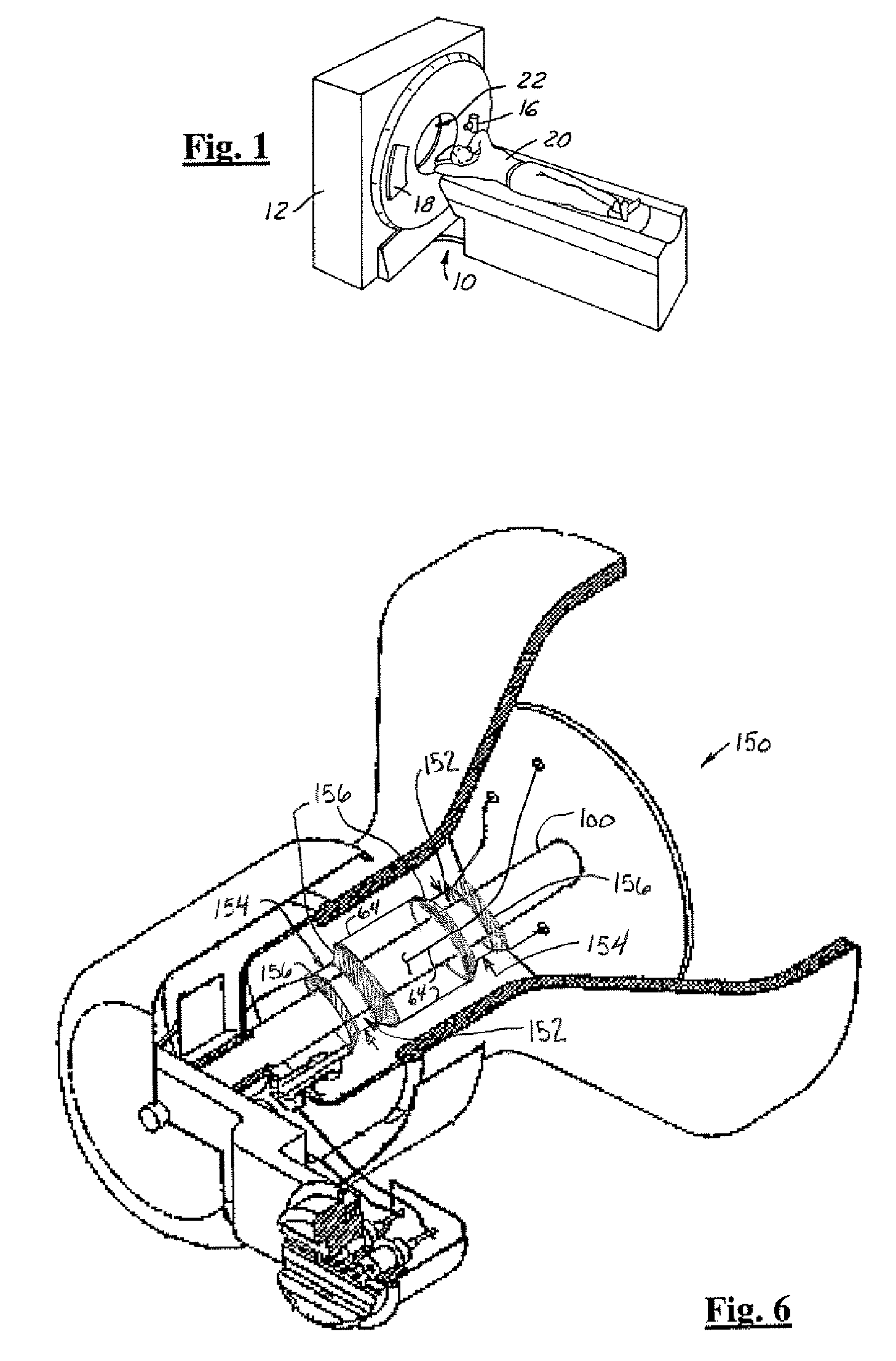
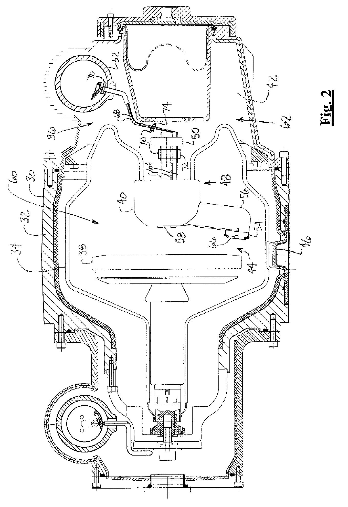
"The present invention provides an apparatus for preventing overvoltage transients in an imaging tube. This is achieved by coupling a voltage-clamping device between the high voltage elements of the imaging tube. The clamping device prevents overvoltage transients, which increases the life of the imaging tube components and increases reliability of the imaging tube. The voltage-clamping devices also serve as insulators for predetermined differential voltage potentials between high voltage elements and protect the high voltage elements from the internal environment of the imaging tube. Additionally, the voltage-clamping devices do not detrimentally affect imaging tube performance and are capable of withstanding physical contact with oil, high temperatures, and high X-ray exposure."

Problems solved by technology

The discharges can cause degradation to the minor insulation on the leads and the cathode cable terminals.
The spit activity causes radiated and conducted electrical noise of high intensity, which can interfere with operations of electronic circuitry in the vicinity of the tube, to the extent of the X-ray system becoming inoperative.
Also, the insulation between the filaments is only capable of protecting against voltage potential discharges of approximately between 1 kV and 5 kV, thus, the filament insulation can also breakdown from the spit activity.
Acceleration of insulation breakdown increases over time and can cause the X-ray system to operate inappropriately and eventually become inoperative.
The overvoltage transients can also cause high voltage degradation to the feedthrough insulators and breakdown in the minor insulation of a high voltage cable between the cathode and the driving circuit.
The loss of high voltage integrity between filaments and common in the high voltage cable can result in instable or uncontrollable high voltage regulation.

Method used


Image

  • X-ray tube cathode overvoltage transient supression apparatus
  • X-ray tube cathode overvoltage transient supression apparatus
  • X-ray tube cathode overvoltage transient supression apparatus

Examples


Embodiment Construction

[0021]In each of the following figures, the same reference numerals are used to refer to the same components. While the present invention is described with respect to an apparatus for suppressing overvoltage transients experienced by a cathode of an imaging tube, the present invention may be adapted to be used in various systems including: radiotherapy systems, X-ray imaging systems, computed tomography systems, and other imaging systems that use imaging tubes.

[0022]In the following description, various operating parameters and components are described for one constructed embodiment. These specific parameters and components are included as examples and are not meant to be limiting.

[0023]Also, in the following description the term “high voltage element” may refer to any high voltage wire, contact, lead, line, filament, pin, or other high voltage element known in the art. A high voltage element may refer to any high voltage contact or electrical conduit between components of an imagin...


PUM


Abstract

An imaging tube (30) includes multiple high voltage elements (64). A voltage-clamping device (70) is coupled between the high voltage elements (64) and prevents the occurrence of overvoltage transients in the minor insulation of an imaging tube (30).

Description

TECHNICAL FIELD[0001]The present invention relates generally to X-ray and computed tomography systems. More particularly, the present invention relates to an apparatus for suppressing the overvoltage transients experienced by a cathode of an X-ray tube.BACKGROUND OF THE INVENTION[0002]An X-ray system typically includes an X-ray tube. The X-ray tube generates X-rays across a vacuum gap between a cathode and a rotating anode structure. In order to generate the X-rays, a filament driving circuit generates thermo-ionic current from the cathode. In releasing of the electrons, the filaments contained within the cathode are heated to incandescence by passing an electric current therein. The electrons are accelerated by the high voltage potential and impinge upon the anode, whereby they are abruptly slowed down to produce X-rays in the form of an X-ray beam.[0003]The high voltage potential across the vacuum gap is typically on the order of 140 kV. Although the filament driving circuit is op...

Claims


Application Information

Patent Timeline
Patent Type & Authority Patents(United States)
IPC IPC(8): H05G1/54
CPCH01J35/025H05G1/54H01J2235/0233
Inventor TANG, LIANG
Owner GE MEDICAL SYST GLOBAL TECH CO LLC
Learn More