Strain relief for ball grid array connectors

a technology of ball grid array and connector, which is applied in the direction of substation/switching arrangement details, coupling device connections, basic electric elements, etc., can solve the problems of unacceptable post receiving through holes in printed circuit boards (pcbs), and surface mounted connectors may also be subjected to uni-directional shear load forces, so as to reduce manufacturing and production costs, the effect of flattening the strain reli

Inactive Publication Date: 2008-03-11
FCI AMERICAS TECH LLC
View PDF46 Cites 21 Cited by
  • Summary
  • Abstract
  • Description
  • Claims
  • Application Information

AI Technical Summary

Benefits of technology

[0004]The invention includes a strain relief device for mounting on a surface of a substrate, wherein the strain relief device is designed to carry a shear load in addition to compensating for CTE mismatches. In one embodiment, the strain relief device may include a spring beam end that deflects during insertion into the strain relief housing and a mount end that may define solder receiving orifices. The resilience of the spring beam and mount end of the device help, alone or in combination, to provide a vertical connector with resistance against a shear force created by an orthogonally connected daughter card. The modularity and flatness of the strain relief device also helps to decrease manufacturing and production costs.
[0006]In an alternative embodiment, an end of the strain relief insert may be inserted into the housing in a direction of insertion until straight beams extending from the insert in a direction perpendicular to the direction of insertion abut shoulders in the slot in the housing. When the beams abut the slot shoulders, the insert may not move further in the direction of insertion, and the end of the insert may extend beyond the strain relief housing. This end may be deformed or bent so that it is perpendicular to the direction of insertion, thus preventing the insert from moving in a direction opposite the direction of insertion. The deformed or bent end may be soldered to a substrate, thereby attaching the strain relief device to the substrate.

Problems solved by technology

However, creating post receiving through holes in a printed circuit board (PCB) is not acceptable in some applications because of the extra manufacturing step and the reduction in usable board space.
However, surface mounted connectors may also be subjected to uni-directional shear load forces caused by orthogonally mated boards, such as a vertical motherboard connector connected to an orthogonally mated daughter card.

Method used


Image

  • Strain relief for ball grid array connectors
  • Strain relief for ball grid array connectors
  • Strain relief for ball grid array connectors

Examples


Embodiment Construction

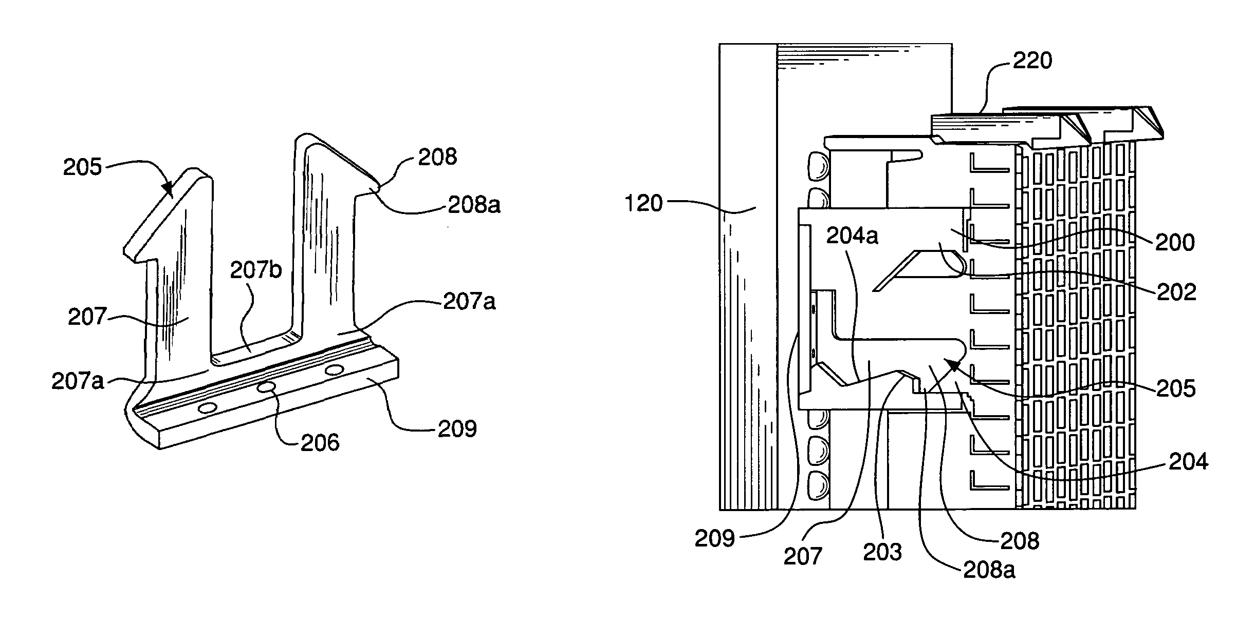
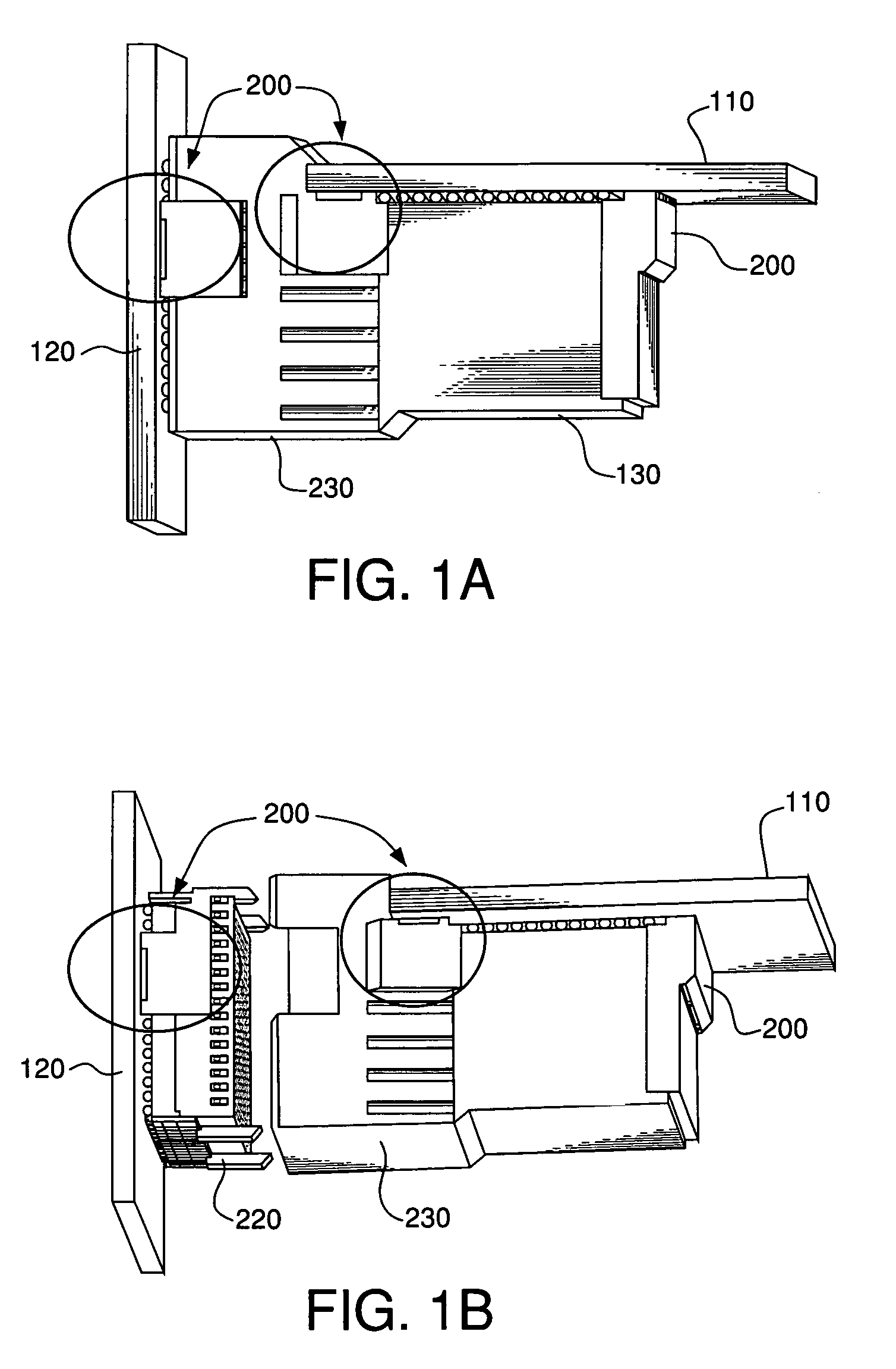
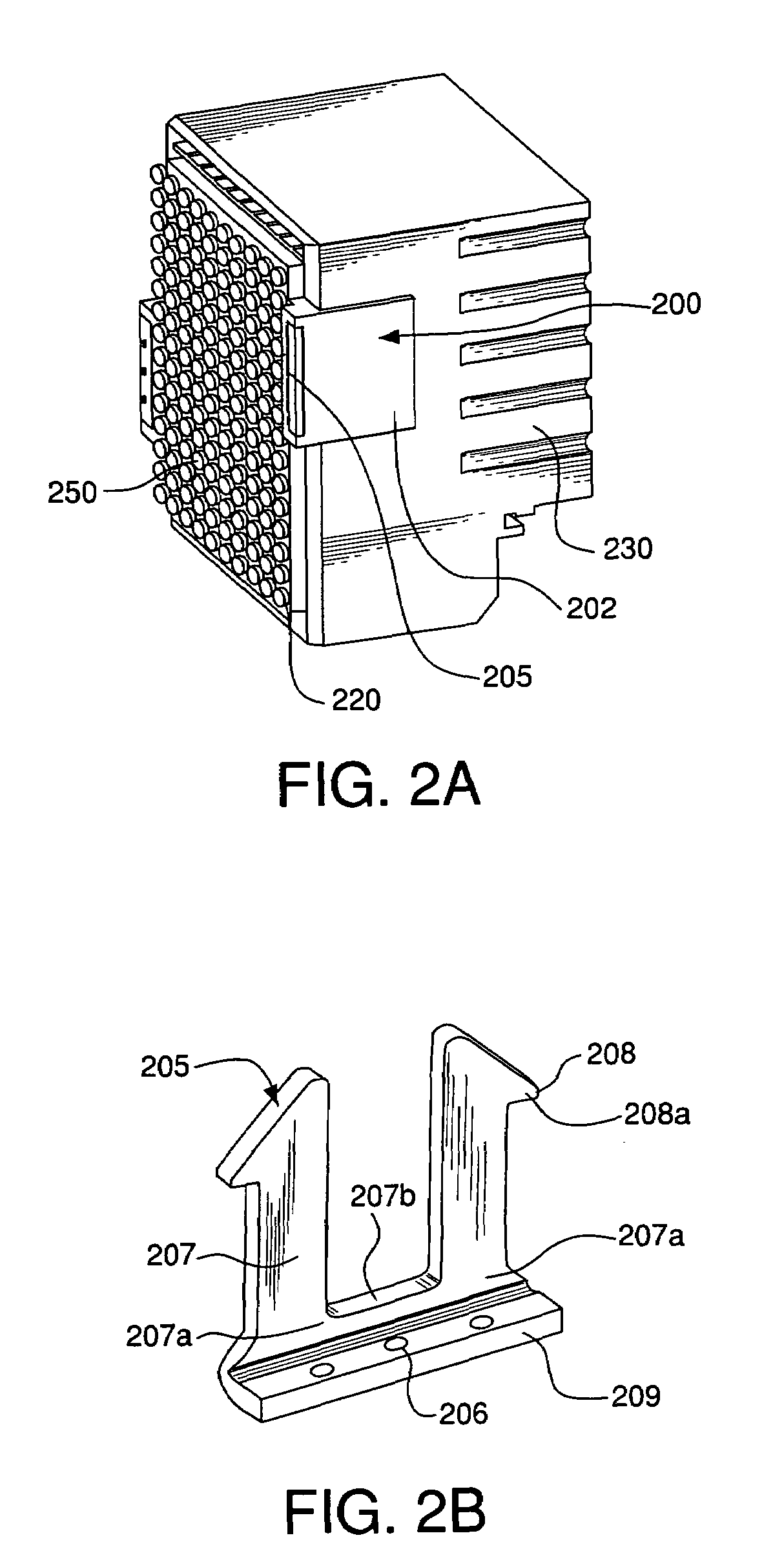
[0020]FIGS. 1A and 1B are perspective views of example strain relief devices 200 connected to respective substrates 110, 120. FIG. 1A shows an electrical connector 130 connecting a substrate 110 to a substrate 120. FIG. 1B depicts an exploded view of the electrical connector 130. The electrical connector 130 may include a receptacle portion 220 and a header portion 230. The receptacle portion 220 may be connected to a substrate 120 such as, for example, a mother board. The header portion may be connected to a substrate 110 such as, for example, a daughter card. That is, the electrical connector 130 may electrically connect a daughter card to a mother board. Those skilled in the art, however, will recognize that embodiments of the invention may be used in any electrical connections between an electrical connector and a substrate.

[0021]The electrical connector 130 may include the strain relief devices 200. Such devices may be attached to or formed as part of a housing of the electrica...


PUM


Abstract

Strain relief devices for electrical connectors are disclosed and include an insert for insertion into a housing. The insert may include spring beams that deflect during insertion into the strain relief housing. When the insert is fully received in the housing, a slot in the housing may be shaped such that the spring beams return to a relaxed state, locking the insert in the housing. Alternatively, an end of a strain relief insert may be inserted into the housing until beams on the strain relief insert abut shoulders in the slot in the housing. The end may protrude beyond the housing, creating a tab that may be deformed or bent to prevent the insert from moving in a direction opposite the direction of insertion.

Description

FIELD OF THE INVENTION[0001]The invention relates generally to electrical connectors. More specifically, the invention relates to relieving strain on electrical connectors connected to substrates.BACKGROUND OF THE INVENTION[0002]Surface mounted electrical connectors may include strain relief mechanisms. Known strain relief mechanisms may take the form of connector posts that extend into a surface of a mounting substrate. However, creating post receiving through holes in a printed circuit board (PCB) is not acceptable in some applications because of the extra manufacturing step and the reduction in usable board space. Therefore, other connectors include a surface mounted strain relief member. For example, U.S. Pat. No. 4,969,829 discloses a strain relief tab that is surface mounted to a substrate.[0003]These strain relief concepts are used to compensate for coefficient of thermal expansion (CTE) mismatches, which in turn can cause electrical connectivity breaks at the intersection of...

Claims


Application Information

Patent Timeline
Patent Type & Authority Patents(United States)
IPC IPC(8): H01R13/73H02B1/01
CPCH01R12/7029H01R12/707
Inventor NGO, HUNG VIET
Owner FCI AMERICAS TECH LLC
Why Eureka
Try Eureka