Integrated circuit cooling apparatus and method

a cooling apparatus and integrated circuit technology, applied in lighting and heating apparatus, instruments, and semiconductor/solid-state device details, etc., can solve the problems of increasing cooling problems, large heat sinks required to disperse the generated heat, and microprocessors that have dramatically increased in speed

Active Publication Date: 2008-03-11
ORACLE INT CORP
View PDF36 Cites 74 Cited by
  • Summary
  • Abstract
  • Description
  • Claims
  • Application Information

AI Technical Summary

Problems solved by technology

Microprocessors have dramatically increased in speed, however, that increase in speed has led to increased cooling problems.
However, as microprocessor speeds increase, the heat sink required to disperse their generated heat may be very large.
This may make thin computers (e.g., laptops) hard or impossible to design.
Additional problems have also been encountered in the quest for smaller computers.
In addition, the smaller enclosures of thinner computing devices may restrict airflow over the heat sink.

Method used


Image

  • Integrated circuit cooling apparatus and method
  • Integrated circuit cooling apparatus and method
  • Integrated circuit cooling apparatus and method

Examples


Embodiment Construction

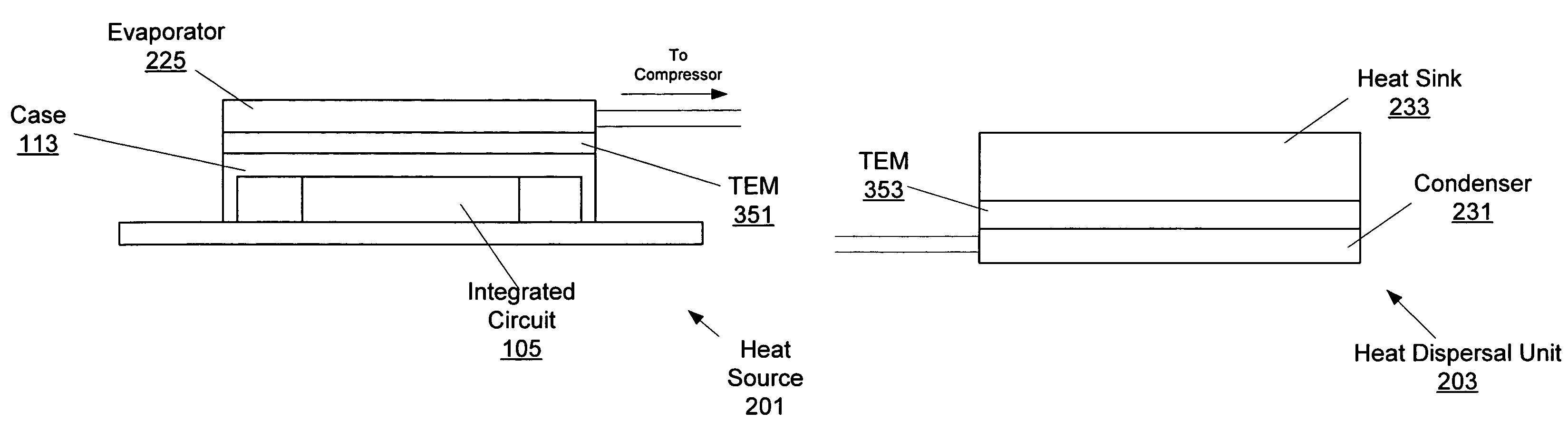
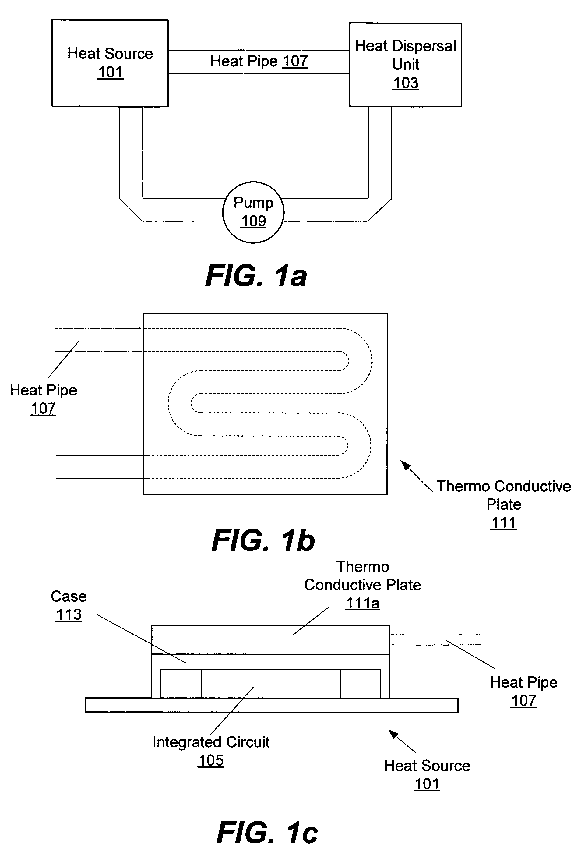
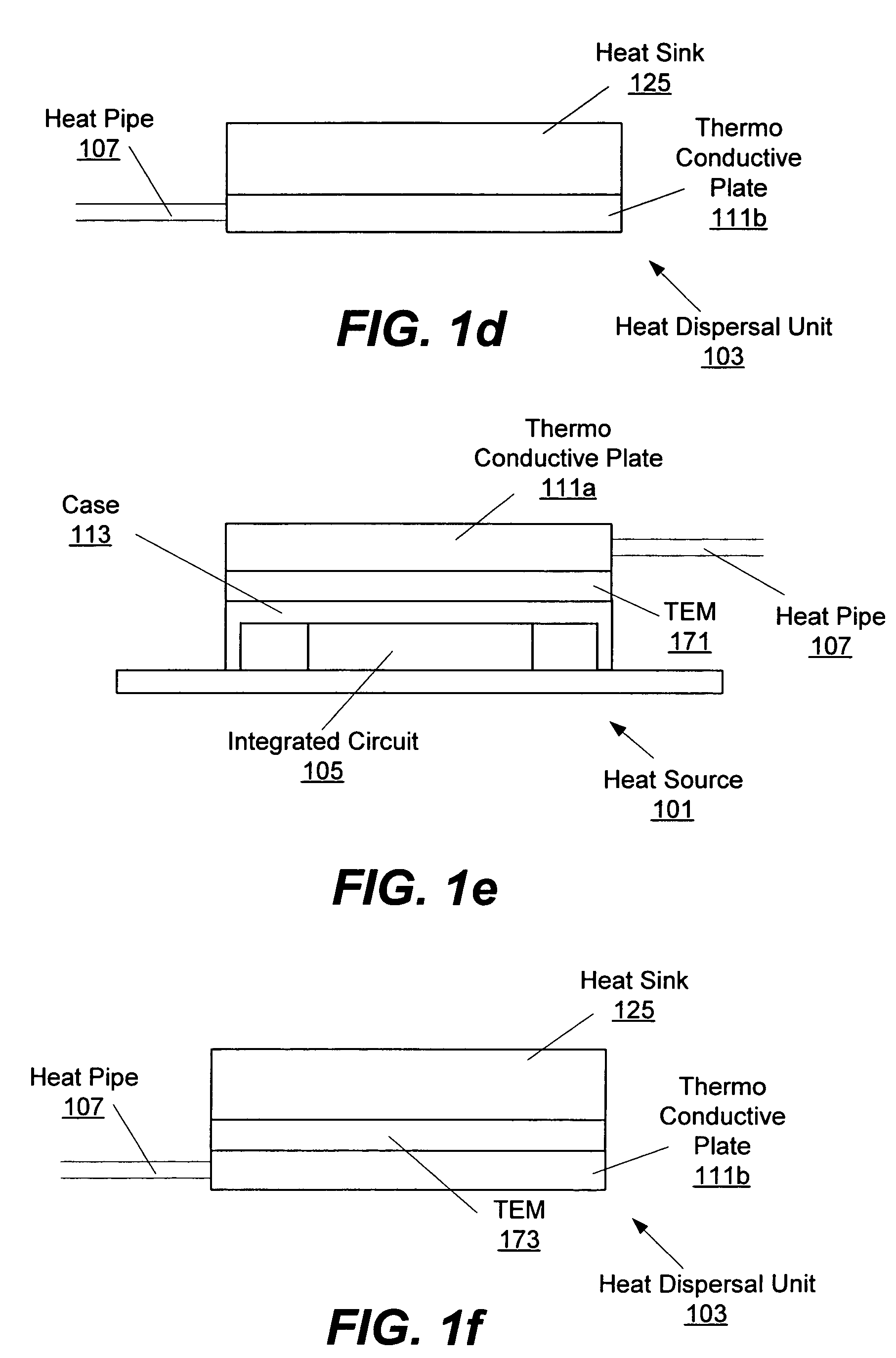
[0018]FIGS. 1a, 1b, 1c, 1d, 1e, and 1f illustrate an embodiment for removing heat from a heat source 101. In some embodiments, the heat source 101 may include an integrated circuit (IC) 105 (e.g., see FIG. 1c) such as a microprocessor. Other heat sources are also contemplated. For example, the heat source 101 may be a power supply or other heat generating component inside a computer system. In some embodiments, e.g., with a microprocessor or other IC, the heat source 101 may be inside of a case 113 (e.g., see FIG. 1c).

[0019]In some embodiments, heat from the heat source 101 may be absorbed into a medium inside a heat pipe 107. To facilitate heat transfer, a thermo conductive plate 111a, made of a conductive material such as aluminum, may couple the heat pipe 107 to the case 113. Other materials for the thermo conductive plate 111 may be used. A top profile of the thermo conductive plate 111 and heat pipe 107 is shown in FIG. 1b. In some embodiments, the thermo conductive plate 111a ...


PUM


Abstract

In various embodiments, heat from a computer component may be absorbed into a medium, moved to a remote heat dispersal unit and dissipated into the surrounding air. In some embodiments, the heat dispersal unit may include a heat sink. In some embodiments, the medium may include a liquid metal. In various embodiments, a vapor compression system may include an evaporator, a compressor, a condenser, and an expansion valve. In some embodiments a separate heat pipe may be placed between the computer component and the evaporator. In various embodiments, a thermo conductive plate may be used to thermally couple the heat pipe to various components including the computer component, evaporator, condenser, and / or heat sink. In some embodiments, a thermo electric module (TEM) may be coupled to various parts of the system.

Description

BACKGROUND OF THE INVENTION[0001]1. Field of the Invention[0002]The present invention relates generally to cooling and, more specifically, to cooling integrated circuits.[0003]2. Description of the Related Art[0004]Microprocessors have dramatically increased in speed, however, that increase in speed has led to increased cooling problems. Microprocessors and other integrated circuits need to be cooled to prevent excessive heat build-up and eventual hardware failure. One solution is to place a heat sink, made of a conductive metal, in thermal contact with the microprocessor. Heat from the microprocessor is conducted to the heat sink and dispersed into the surrounding air. Fans may also be used to move air over the heat sinks to further enhance their cooling rate. Heat sinks may also include fins to increase the surface area of the heat sink in contact with the air to further enhance cooling.[0005]However, as microprocessor speeds increase, the heat sink required to disperse their gene...

Claims


Application Information

Patent Timeline
Patent Type & Authority Patents(United States)
IPC IPC(8): H05K7/20
CPCG06F1/203H01L23/427F28D15/0266G06F2200/201H01L2924/0002H01L2924/00
Inventor BHATIA, RAKESH
Owner ORACLE INT CORP
Why Eureka
Try Eureka