
Array processing using an aggregate channel matrix generated using a block code structure

a block code and channel matrix technology, applied in the field of wireless communication, can solve the problems of interference between each other, power and bandwidth are limited, and battery life is limited,

Active Publication Date: 2008-03-11
LUCENT TECH INC
View PDF4 Cites 17 Cited by
  • Summary
  • Abstract
  • Description
  • Claims
  • Application Information

AI Technical Summary

Benefits of technology

"The present invention provides a method and system for processing signals over a channel. The method involves generating a received signal vector with symbols encoded in a block code, transforming the channel matrix based on the structure of the block code to create an aggregate channel matrix, and processing the symbols using this matrix. The technical effect of this invention is improved signal processing and more accurate channel estimation, leading to better quality signal transmission."

Problems solved by technology

However, both power and bandwidth are limited by certain entities such as governmental and standards organizations that regulate such factors.
In addition, for portable devices, power is limited by battery life.
These multiple paths interfere with each other at the location of the receive antenna.
However, in many cases the amount of space available for the antenna array is limited.
In particular, the space limitation is very critical for portable wireless devices (e.g., cell phones, Personal Digital Assistants (PDAs), and the like).
Signal correlation reduces the gain in information transfer rate obtained by the use of MIMO techniques.
Accordingly, the wait time required to receive all the codewords prior to decoding increases, resulting in greater latency.
Also, longer codewords require greater computational complexity.

Method used


Image

  • Array processing using an aggregate channel matrix generated using a block code structure
  • Array processing using an aggregate channel matrix generated using a block code structure
  • Array processing using an aggregate channel matrix generated using a block code structure

Examples


Embodiment Construction

[0019]Illustrative embodiments of the invention are described below. In the interest of clarity, not all features of an actual implementation are described in this specification. It will of course be appreciated that in the development of any such actual embodiment, numerous implementation-specific decisions must be made to achieve the developers' specific goals, such as compliance with system-related and business-related constraints, which will vary from one implementation to another. Moreover, it will be appreciated that such a development effort might be complex and time-consuming, but would nevertheless be a routine undertaking for those of ordinary skill in the art having the benefit of this disclosure.

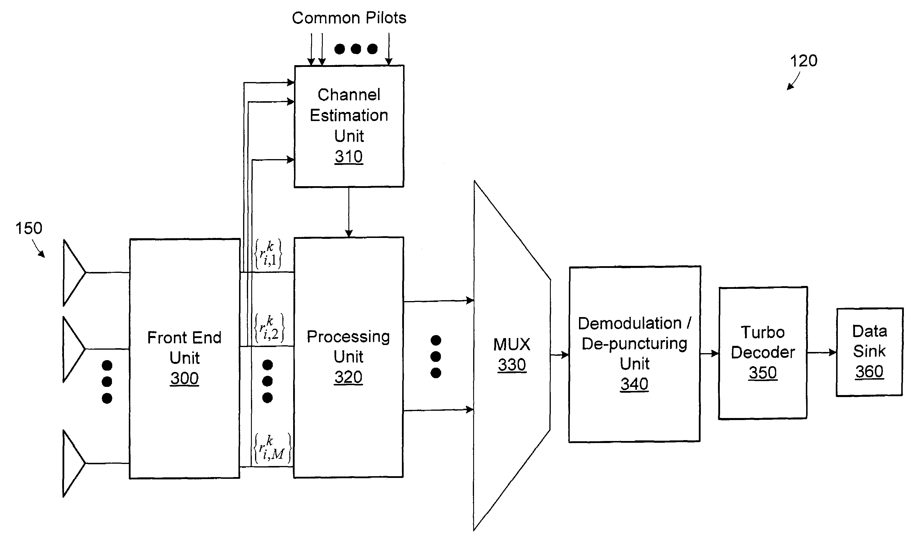
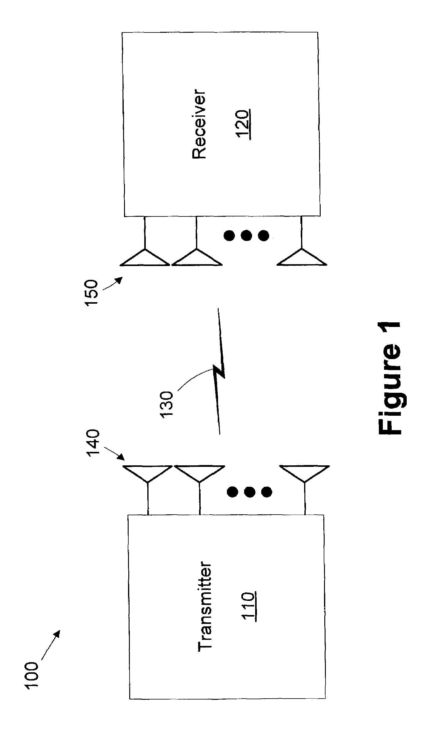
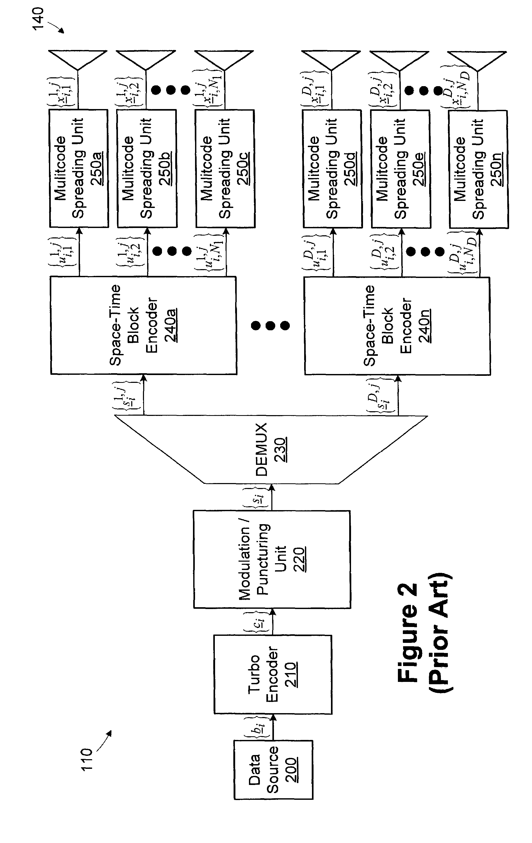
[0020]Referring now to FIG. 1, a simplified block diagram of a communications system 100 in accordance with one embodiment of the present invention is provided. A transmitter 110 communicates with a receiver 120 over a channel 130. The transmitter 110 and receiver 120 employ mult...


PUM


Abstract

A method includes generating a received signal vector from a signal received over a channel. The received signal vector includes a plurality of symbols encoded in accordance with a block code having a structure. A channel matrix estimated for the channel is transformed based on the structure of the block code to generate an aggregate channel matrix. The symbols are processed using the aggregate channel matrix. A system includes a front end unit configured to generate the received signal vector, a channel estimation unit configured to estimate the channel matrix, and a processing unit configured to generate the aggregate channel matrix and process the symbols using the aggregate channel matrix.

Description

BACKGROUND OF THE INVENTION[0001]1. Field of the Invention[0002]This invention relates generally to the field of wireless communication using a space-time block coded (STBC) multiple input multiple output (MIMO) scheme and, more particularly, to array processing using an aggregate channel matrix generated using a space-time block code structure.[0003]2. Description of the Related Art[0004]Owners and / or operators of communication networks, i.e., the service providers, are constantly searching for methods and equipment that can meet the changing needs of their subscribers. Subscribers of communication networks, including wireless communication networks, require higher information throughput in order to exploit the expanding range of services being provided by current communication networks. For example, wireless communication subscribers are now able to have simultaneous access to data networks such as the Internet and to telephony networks such as the Public Switched Telephone Networ...

Claims


Application Information

Patent Timeline
Patent Type & Authority Patents(United States)
IPC IPC(8): H04L27/00H04L1/06
CPCH04L1/0618
Inventor LIU, JUNG-TAO
Owner LUCENT TECH INC
Learn More