Image information compression device

a compression device and image information technology, applied in the field of encoded and compressed image information, can solve the problems of insufficient quantity of code allotted to the later frame, so-called frame omission, and large quantity of information is instantly generated, so as to minimize the degradation of image quality, improve image quality, and be easily visible

Active Publication Date: 2008-03-11
TEXAS INSTR INC
View PDF4 Cites 8 Cited by
  • Summary
  • Abstract
  • Description
  • Claims
  • Application Information

AI Technical Summary

Benefits of technology

[0011]When the quantizing coefficient is used as the parameter, the filter coefficients are preferably selected to limit the high-frequency component more when the value of the quantizing coefficient is larger, that is, when the quantizing resolution is coarser. As a result, relatively more codes are allotted to the low-frequency component that is important for viewing, thus minimizing degradation in the image quality. In this adaptive control a rate control unit selects the quantizing coefficients used in the quantizing unit in order to control the bit rate of the encoded data output from the encoding unit.
[0012]When the luminance value of the transform block is selected as the parameter, the filter coefficients are preferably selected to limit the high-frequency component more when the luminance value of the transform block approaches the lower limit value or the upper limit value. Excess codes are thus allotted to the intermediate luminance value region which is prone to significant degradation in the image quality. Thus the image quality is improved. In such adaptive control, a block luminance detection unit detects the luminance value of the transform block on the basis of the luminance component of the pixel data of that transform block.
[0013]When the position of the block in the frame is taken as the parameter, the filter coefficients are preferably selected to limit the high-frequency component more when the transform block belongs to the peripheral portion of a prescribed range in the frame. Excess codes are thus allotted to the region at the center of the picture where degradation in the image quality is easily visible, improving the overall image quality. In such adaptive control, a block position detector detects the position of the transform block in the frame during block division processing in the block division unit.

Problems solved by technology

However, when a scene change takes place or when there is a significant change in the image, a huge quantity of information is instantly generated.
Consequently, an insufficient quantity of code may be allotted to the later frames.
This may result in a so-called frame omission.
The number of frames per second must be reduced, significantly degrading the image quality.
This is undesirable.

Method used


Image

  • Image information compression device
  • Image information compression device
  • Image information compression device

Examples


Embodiment Construction

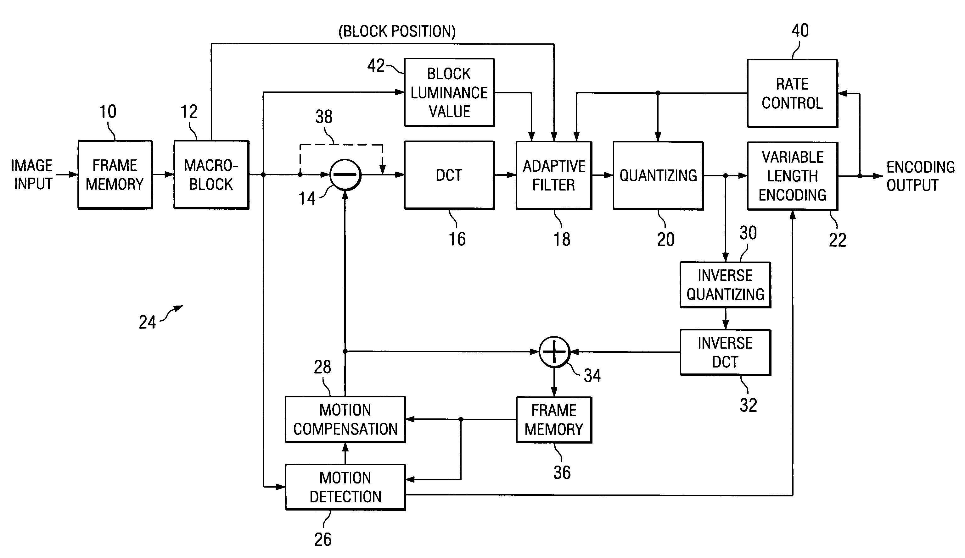
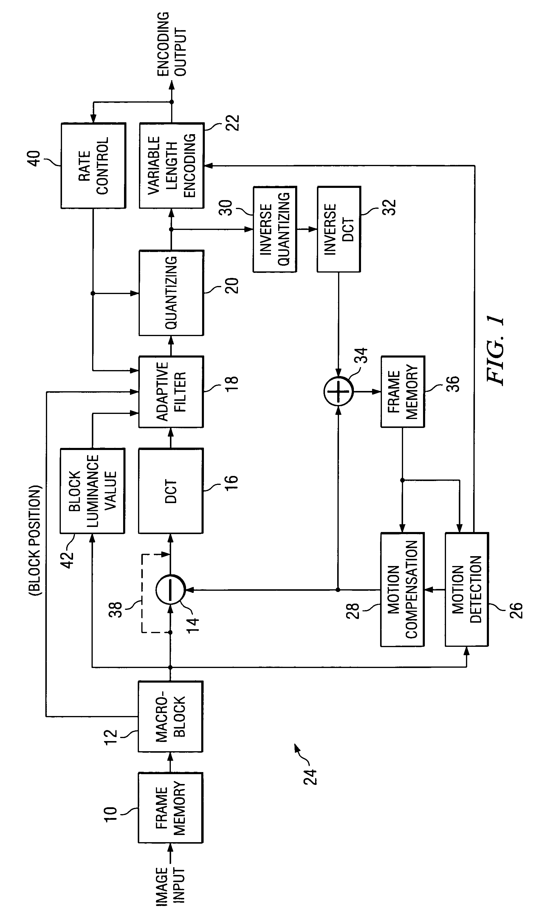
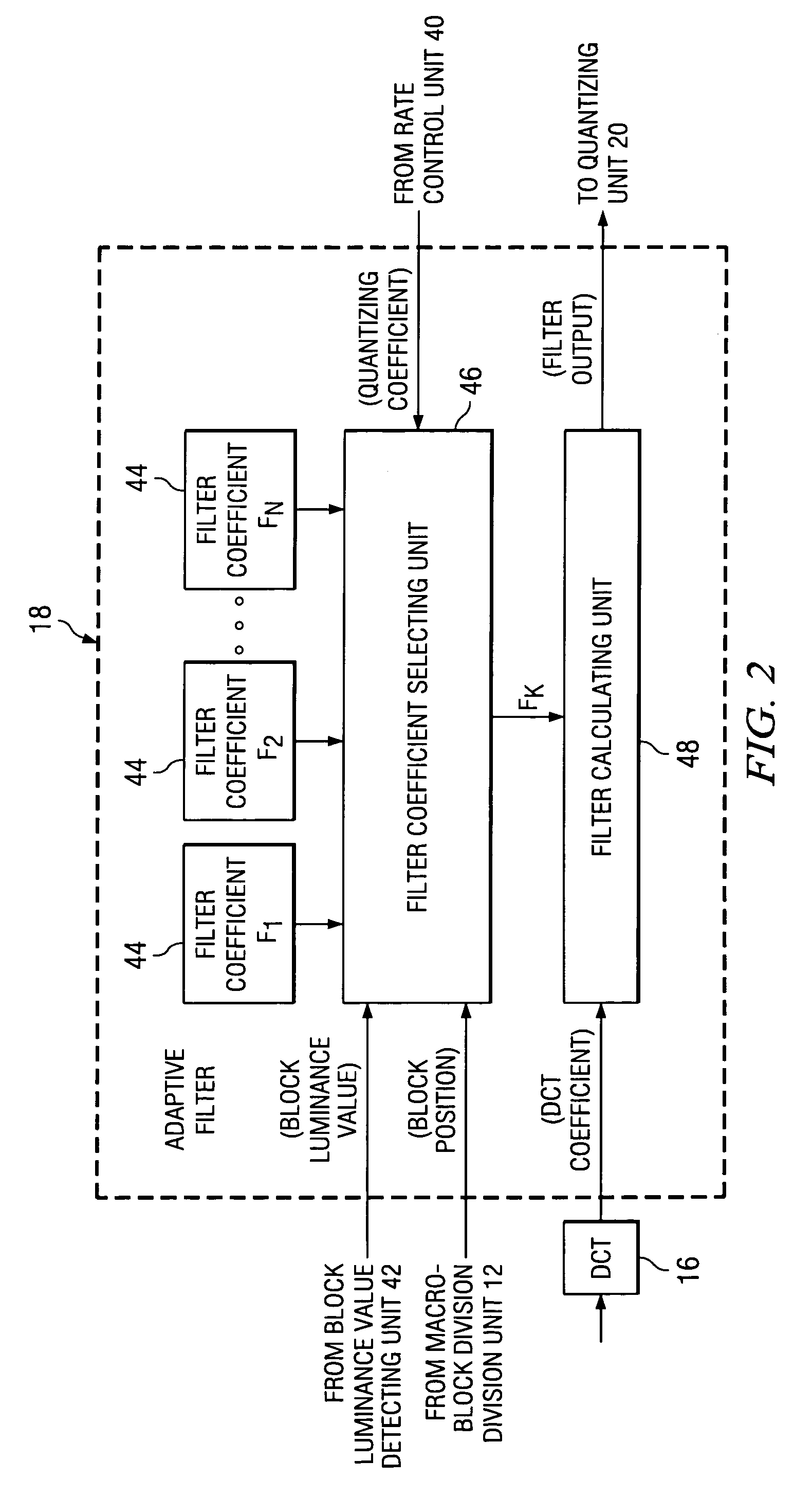
[0029]In the following, preferred embodiments of this invention will be explained with reference to appended Figures. These Figures illustrate: frame memory 10; macro-block division unit 12; difference calculation unit 14; DCT transform unit 16; adaptive filter 18; quantizing unit 20; variable length encoding unit 22; local decoding unit 24; motion detection unit 26; motion compensation unit 28; inverse quantizing unit 30; inverse DCT transform unit 32; adder 34; frame memory 36; rate control unit 40; block luminance value detection unit 42; coefficient table memory 44; filter coefficient selecting unit 46; and filter calculating unit 48.

[0030]FIG. 1 illustrates the image information compression device in one embodiment of this invention. This image information compression device is an encoder that performs information compression of moving pictures using both DCT and motion compensation.

[0031]Frame memory 10 receives a digital image signal or moving picture image data from a video ...


PUM


Abstract

This invention controls the code generation quantity adaptively with respect to the pattern of images and changes in the images, etc., so as to alleviate degradation in image quality, and to effectively reduce the spatial redundancy in order to provide a margin in the code quantity and to improve the overall image quality. An adaptive filter has a coefficient table memory that holds N coefficient tables, filter coefficients F1, F2 . . . FN that provide different filtering characteristics, a filter coefficient selecting 46 for selecting one filter coefficient Fk from filter coefficient tables and filter calculating unit performing prescribed calculations on the DCT coefficients using the selected filter coefficient FK.

Description

TECHNICAL FIELD OF THE INVENTION[0001]The technical field of this invention is encoding and compressing image information using an orthogonal transform encoding algorithm.BACKGROUND OF THE INVENTION[0002]When images are digitized, the image information is usually encoded and compressed. An effective method for compressing the image information is to reduce the spatial redundancy contained in the image. These methods typically use the well-known discrete cosine transform (DCT). The input image data are divided into blocks of, for example, 8 pixels by 8 lines. A 2-dimensional DCT is applied to generate DCT transform coefficients with the correlation between pixels removed. Usually, these coefficients are quantized to integer values with finite precision (bit length) and then converted into a bit sequence of binary codes employing variable length encoding such as Huffman codes.[0003]When a moving picture is digitized, temporal information compression is also carried out in addition to ...

Claims


Application Information

Patent Timeline
Patent Type & Authority Patents(United States)
IPC IPC(8): G06K9/36G06K9/46H04N19/50H04N19/117H04N19/126H04N19/136H04N19/167H04N19/176H04N19/46H04N19/503H04N19/51H04N19/60H04N19/61H04N19/625H04N19/70H04N19/80H04N19/85H04N19/91
CPCH04N19/176H04N19/134H04N19/115H04N19/61H04N19/117H04N19/82H04N19/136H04N19/152H04N19/17H04N19/48H04N19/124
Inventor ONUMA, HIDETOSHIMUROHASHI, KOHICHI
Owner TEXAS INSTR INC
Why Eureka
Try Eureka