Method of manufacturing perpendicular magnetic recording head capable of highly precisely defining gap distance

a technology of perpendicular magnetic recording head and manufacturing method, which is applied in the direction of magnetic bodies, manufacturing tools, instruments, etc., can solve the problem of difficult control of the gap distance at the accomplishment state of the recording head

Inactive Publication Date: 2008-03-18
TDK CORPARATION
View PDF4 Cites 32 Cited by
  • Summary
  • Abstract
  • Description
  • Claims
  • Application Information

AI Technical Summary

Benefits of technology

[0016]According to this embodiment, since the rising angle (throat shape) of the end surface of the rear side in the height direction of the return path layer is in two stages, the gap distance becomes wider at the rear side in the height direction than at the medium facing surface, and the writing performance (recording magnetic field strength) may be controlled with a good balance. The magnitude relation of the rising angles of the upper gap layer and the resist layer is properly set according to the desired recording resolution and the writing performance.
[0019]According to the a present embodiment, since the lower gap layer is protected by the upper gap layer, while not suffering damage by the etching or the developing solution during the manufacturing process, it can obtain a method of manufacturing a perpendicular magnetic recording head of which the gap distance is very accurately defined by the thickness during forming film of the lower gap layer.

Problems solved by technology

In a manufacturing method of the related art, since the gap layer made of Al2O3 is eroded by the alkali developing solution used in the photolithography process in removing of the resist layer, and the gap layer is cut by the dry etching, which performs as a pre-treatment in forming of the plated underlayer or the coil layer, the film thickness of the gap layer becomes thinner in accordance with the passage of the manufacturing process, and it is difficult to control the gap distance at the accomplishment state of the head.

Method used


Image

  • Method of manufacturing perpendicular magnetic recording head capable of highly precisely defining gap distance
  • Method of manufacturing perpendicular magnetic recording head capable of highly precisely defining gap distance
  • Method of manufacturing perpendicular magnetic recording head capable of highly precisely defining gap distance

Examples


Embodiment Construction

[0027]Preferred embodiments will now be described with reference to the drawings.

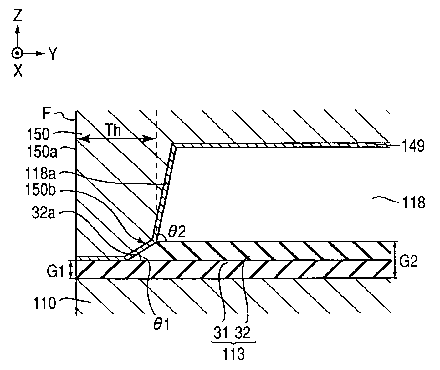
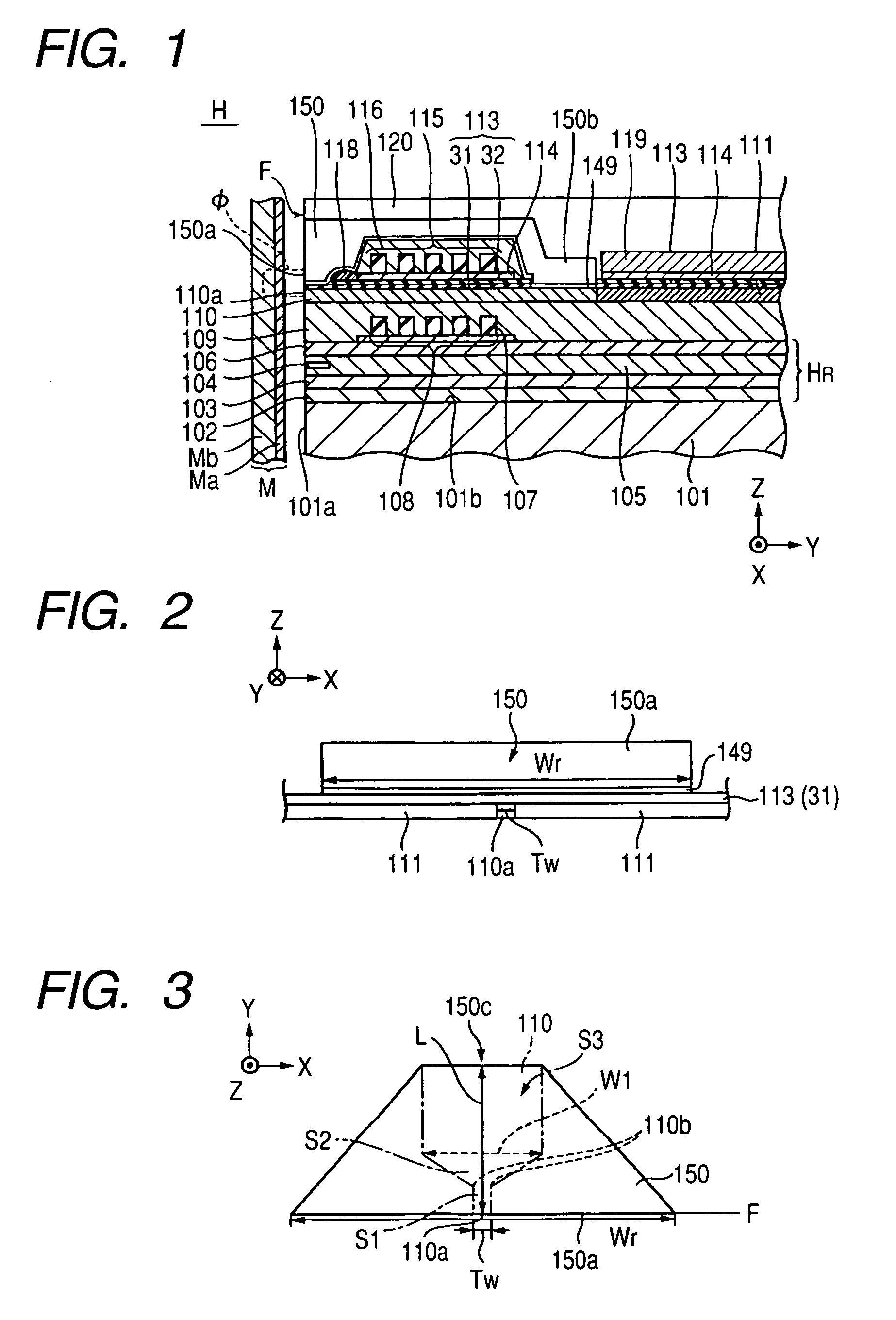
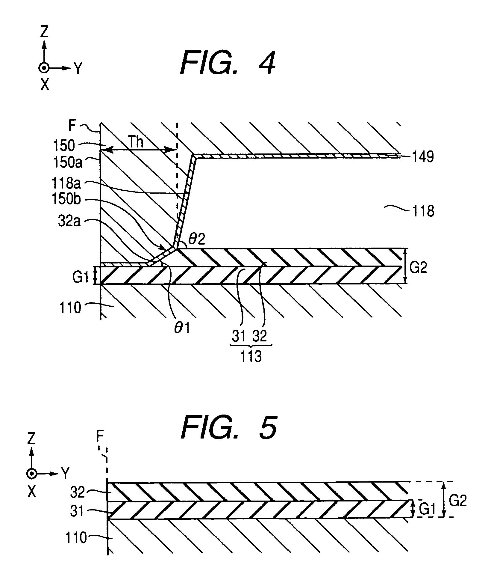
[0028]In FIGS. 1 to 4, the X direction, the Y direction, and the Z direction define a width direction of a track, a height direction (=leakage magnetic field direction from the recording medium M), and a shift direction of the recording medium M, respectively.

[0029]A magnetic head H applies a perpendicular magnetic field to the recording medium M so as to magnetize a hard film Ma of the recording medium M in a direction perpendicular thereto. The recording medium M is composed of the hard film Ma, which has a high residual magnetization and is provided at a surface of the medium, and a soft film Mb, which has a high magnetic transmittance and is provided at a side more near the rear side than the hard film Ma. The recording medium M is, for example, in the form of a disc, and the recording medium M rotates around the center of the disc serving as a rotational axis.

[0030]A slider 101 is formed of a non-m...


PUM

PropertyMeasurementUnit
thicknessaaaaaaaaaa
thicknessaaaaaaaaaa
gap distance G1aaaaaaaaaa

Abstract

A method of manufacturing a perpendicular magnetic recording head is provided. The method accurately defines a gap layer. The method includes forming a lower gap layer made of a non-magnetic material on a main magnetic pole layer. An upper gap layer is formed on the lower gap layer, the upper gap layer being made of the non-magnetic material. A resist layer is formed on the upper gap layer, and the resist layer is removed from an end surface. The upper gap layer not covered with the resist layer is removed, while exposing a new film surface by removing a surface oxidation layer of the resist layer. A return path layer is formed by plating on the exposed lower gap layer, the upper gap layer, and the resist layer through the plating underlayer.

Description

[0001]This application claims the benefit of Japanese Patent Application No. 2005-278283 filed on Sep. 26, 2005, which is hereby incorporated by this reference.BACKGROUND[0002]1. Field[0003]The present embodiments relate to a perpendicular magnetic recording head that performs a recording operation.[0004]2. Related Art[0005]A magnetic head device includes a longitudinal recording (in-plane recording) magnetic head device that applies a magnetic field parallel to a plane of a recording medium thereto to perform a recording operation, and a perpendicular magnetic recording head device that applies a magnetic field perpendicular to a plane of the recording medium thereto to perform a recording operation. The perpendicular magnetic recording head device is further suitable to increase the recording density.[0006]Conventionally, the perpendicular magnetic recording head has a structure in which a main magnetic pole layer and a return path layer are laminated with a non-magnetic insulatin...

Claims


Application Information

Patent Timeline
Patent Type & Authority Patents(United States)
IPC IPC(8): G11B5/127H04R31/00
CPCG11B5/1278G11B5/3116G11B5/3163Y10T29/49046Y10T29/49052Y10T29/49039Y10T29/49044Y10T29/49071Y10T29/49043Y10T29/49073Y10T29/49048
Inventor KOBAYASHI, KIYOSHI
Owner TDK CORPARATION
Why Eureka
Try Eureka