Torsional vibration damper

a torsional vibration damper and damper technology, applied in the direction of spring/damper, rotational vibration suppression, vibration suppression adjustment, etc., can solve the problem of resonance magnification factor, the degree of isolation of the torsional vibration damper is no longer sufficient for many driving conditions, and the springs of the power accumulator may at least no longer completely relax, etc. problem, to achieve the effect of low pivot elasticity, low cost and low cos

Inactive Publication Date: 2008-03-18
SCHAEFFLER TECH AG & CO KG
View PDF29 Cites 16 Cited by
  • Summary
  • Abstract
  • Description
  • Claims
  • Application Information

AI Technical Summary

Benefits of technology

[0004]The present invention is based on an object of optimizing torsional vibration dampers of the above-mentioned type in regard to their damping properties. An additional or alternative objective according to the present invention is that the torsional vibration damper may be manufactured and installed in an especially simple way. In particular, it is desired that even at relatively high rotational speeds of the torsional vibration damper, its energy accumulators, which may be formed by helical compression springs in particular, may fulfill their assigned function optimally.
[0005]The present invention provides a torsional vibration damper of the type initially described in that the at least one spring is received in a carrier part, which has at least a limited capability to pivot in relation to both parts which are pivotable toward one another, the end regions of the spring being supported in the carrier in such a way and the carrier being implemented in such a way that the intermediate region of the spring provided between these end regions remains contactless—at least up to a limiting rotational speed—in relation to regions of at least one component which overlap these spring intermediate regions radially on the outside. Through a design of this type, it is ensured that the spring received in the carrier, which may preferably be formed by a helical compression spring, may operate and / or be compressed practically frictionlessly. Through a design of this type, it may be ensured that the spring rate or elasticity and / or the spring travel of the spring is practically uninfluenced by the centrifugal force acting thereon. Through a design of the torsional vibration damper of this type, it may be ensured that at least up to a specific limiting rotational speed there is a sufficiently low pivot elasticity and / or a sufficiently small pivot resistance between the damper input part and the damper output part over a specific pivot angle that the occurrence of resonance effects and / or interfering noises is prevented or at least reduced to an acceptable level. In this way, the driving comfort of a motor vehicle may be significantly improved.
[0006]In an especially advantageous way, the carrier which receives at least one spring may be positioned inside the torsional vibration damper in such a way that this spring is only active during motor braking. The at least one spring received in a carrier part therefore does not have to be designed for the idle range of an internal combustion engine which works together with a torsional vibration damper designed according to the present invention, but rather is designed for the load range of the torsional vibration damper in particular.

Problems solved by technology

Problems in regard to the vibration isolation may often be attributed to the damping effect of the rotationally elastic damper provided between the damper input part and damper output part being dynamically influenced, because friction, which acts in parallel to the spring effect of the energy accumulator and increases with increasing rotational speed, is generated due to the centrifugal forces acting on the energy accumulator of the damper.
Friction of this type occurs in particular if the energy accumulators provided between the damper input part and damper output part include power accumulators which are formed by helical compression springs having a large length / coil diameter ratio.
Specifically, with increasing rotational speed, the above-mentioned friction damping may increase enough in power accumulators of this type that the springs of the power accumulators may at least no longer completely relax.
This increase in the torsional stiffness between the input part and output part of the torsional vibration damper caused by the centrifugal force and / or the power accumulators may lead to the degree of isolation of the torsional vibration damper no longer being sufficient for many driving conditions, so that resonance magnification factors may occur.

Method used


Image

  • Torsional vibration damper
  • Torsional vibration damper
  • Torsional vibration damper

Examples


Embodiment Construction

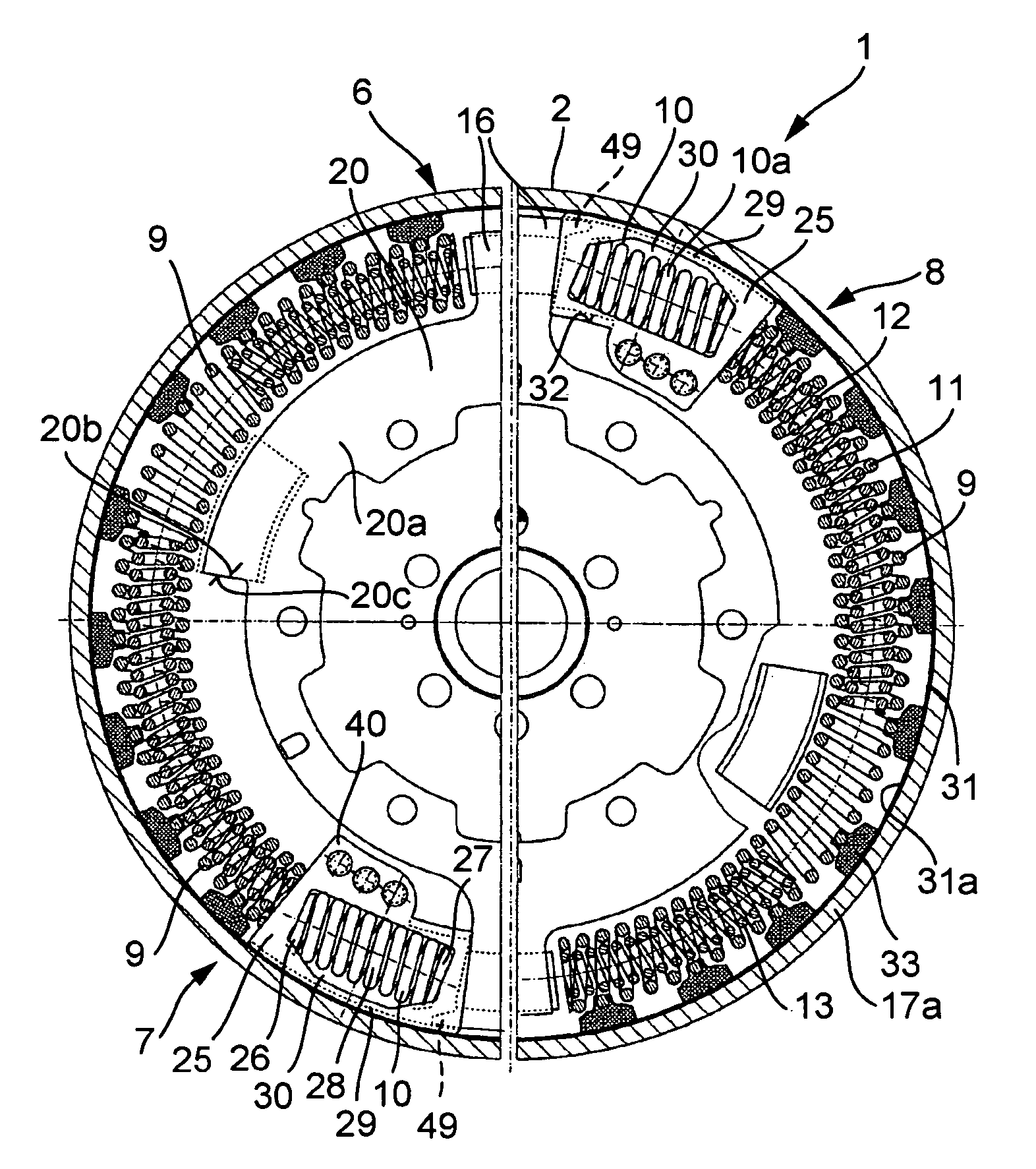
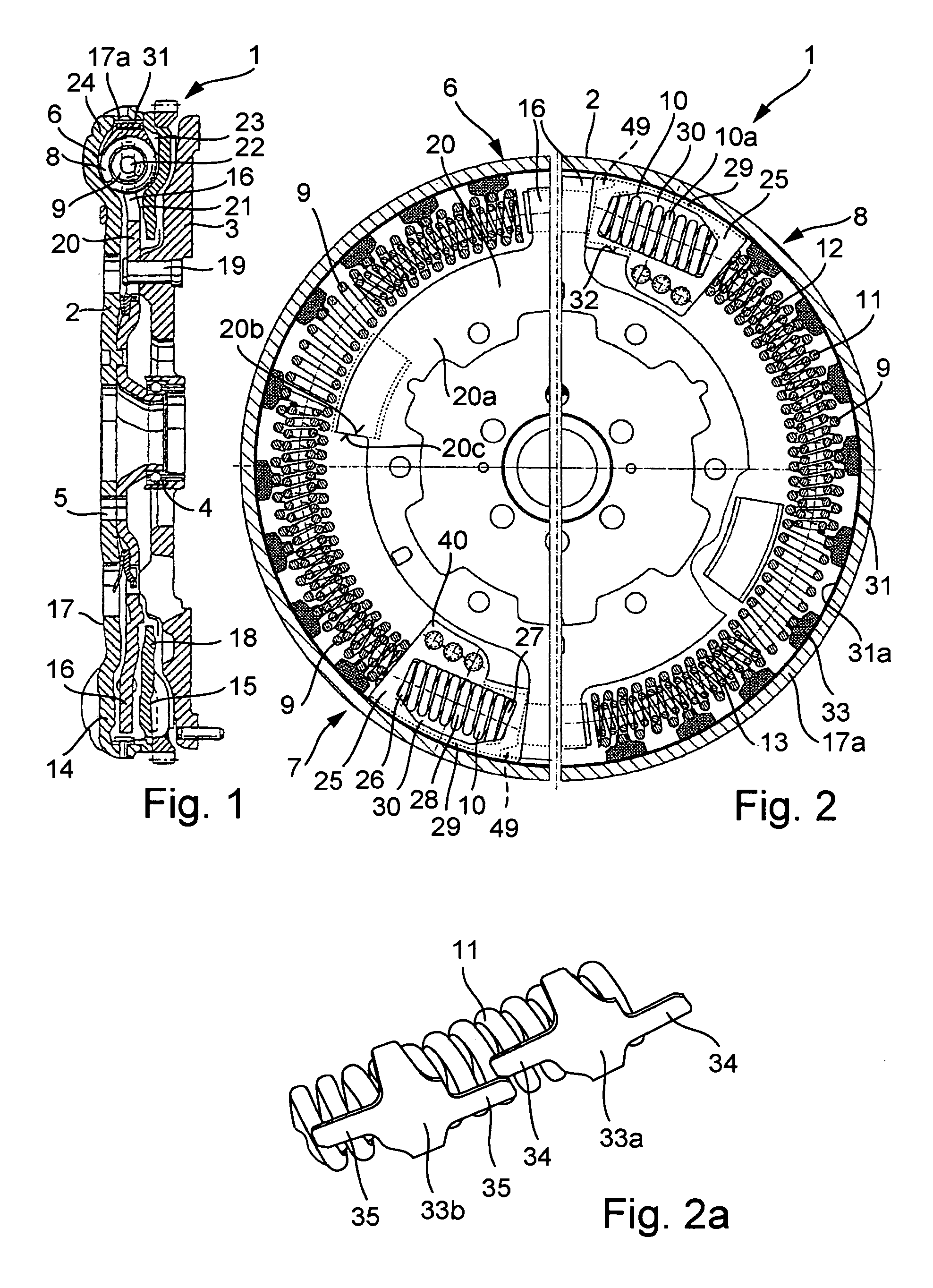
[0024]The torsional vibration damper shown in FIGS. 1 and 2 in section forms a split flywheel 1, which has a first or primary flywheel mass 2, attachable to a drive shaft of an internal combustion engine, and a second or secondary flywheel mass 3. A friction clutch may be attachable to second flywheel mass 3 with a clutch disk interposed, via which an input shaft of a transmission may be coupled and decoupled. Flywheel masses 2 and 3 are mounted pivotably in relation to one another via a bearing 4, which, in the exemplary embodiment shown, is positioned radially inside holes 5 for guiding through attachment screws for installing first flywheel mass 2 on the output shaft of an internal combustion engine. A damping device 6 is active between both flywheel masses 2 and 3. Damping device 6 shown in FIG. 2 has two energy accumulators 7, 8, each of which is formed by two power accumulators 9 and 10 connected in series.

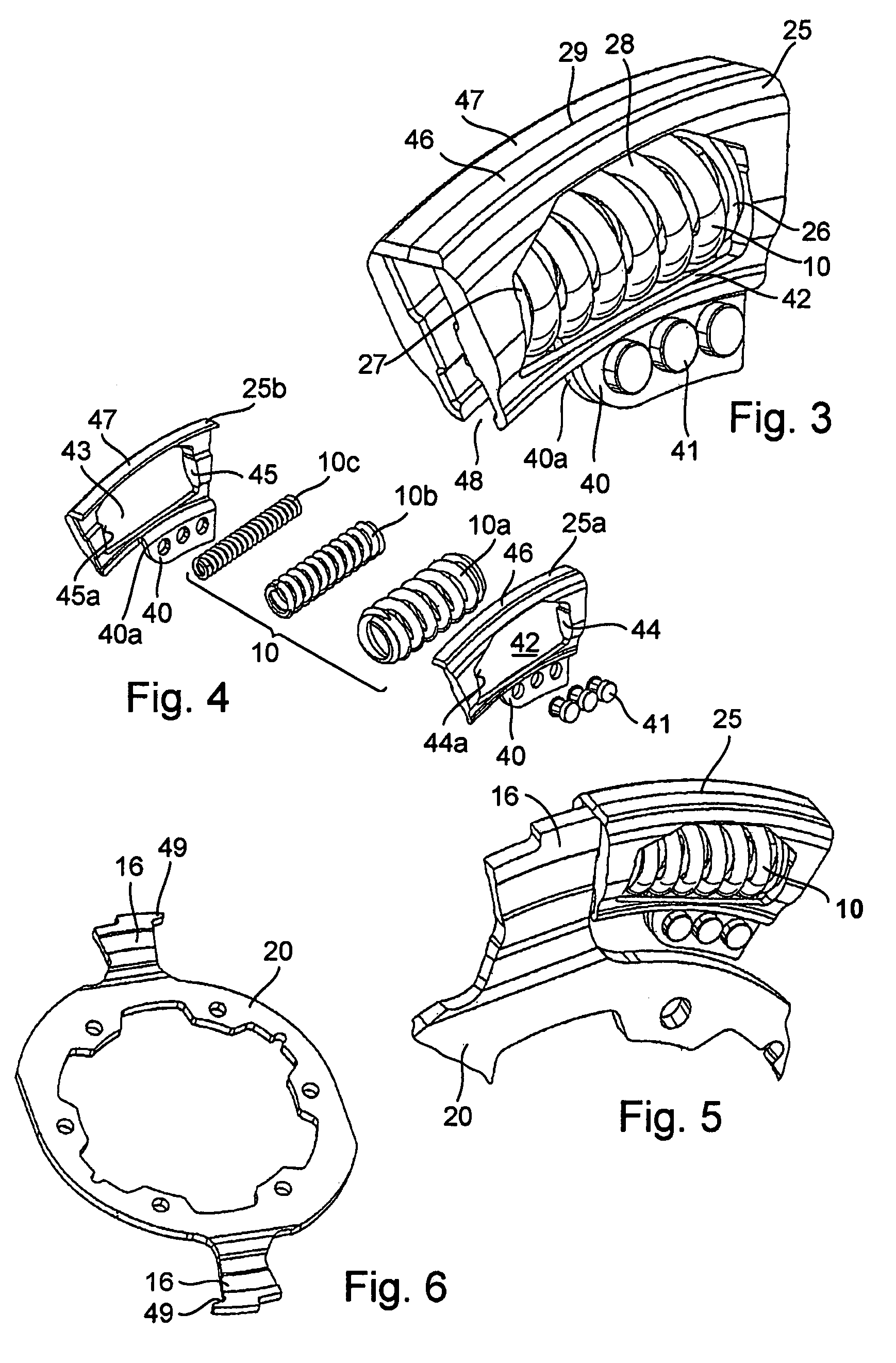
[0025]In the exemplary embodiment shown, power accumulator 9 includes m...


PUM


Abstract

A torsional vibration damper is described having at least two parts rotatable around an axis of rotation, which are pivotable toward one another against the effect of at least one energy accumulator, the parts pivotable toward one another having regions using which the energy accumulator, which acts around the circumference of the torsional vibration damper, is compressible, the energy accumulator having at least one spring held in a carrier.

Description

[0001]This claims the benefit of German Patent Application No. 103 06 163.0, filed Feb. 14, 2003 and hereby incorporated by reference herein.BACKGROUND INFORMATION[0002]The present invention relates to a torsional vibration damper, for motor vehicles in particular, having at least two parts, rotatable around a rotational axis, which are pivotable toward one another against the effect of at least one energy accumulator, the parts which are pivotable toward one another having regions using which the energy accumulator, which acts around the circumference of the torsional vibration damper, is compressible, this energy accumulator being formed by at least one spring, such as a helical compression spring.[0003]Torsional vibration dampers of this type in the form of dual-mass flywheels have become known, for example, from German Patent Application Nos. 41 17 582 A1, 42 14 655 A1, 44 14 584 A1, 44 20 927A1, and 195 22 718 A1, which relate respectively to U.S. Pat. Nos. 5,150,777 and 5,310,...

Claims


Application Information

Patent Timeline
Patent Type & Authority Patents(United States)
IPC IPC(8): F16F15/12F16F15/134
CPCF16F15/1343Y10T74/2125
Inventor JAECKEL, JOHANNMENDE, HARTMUT
Owner SCHAEFFLER TECH AG & CO KG
Why Eureka
Try Eureka