Method of and apparatus for generating phase contrast image

a technology of phase contrast and image, applied in the field of method and apparatus for generating phase contrast image, can solve the problems of difficult to precisely generate a phase contrast image, small contrast obtained in image, poor information, errors in phase contrast image, etc., and achieve the effect of preventing the shift of position due to the mismatch of radiation image sizes

Inactive Publication Date: 2008-03-18
FUJIFILM CORP +1
View PDF5 Cites 34 Cited by
  • Summary
  • Abstract
  • Description
  • Claims
  • Application Information

AI Technical Summary

Benefits of technology

[0031]In accordance with the method and the apparatus of the present invention, position shift due to mismatch of the sizes of the radiation images can be prevented since an enlargement / reduction processing is carried out on the radiation images as taken in the imaging positions according to the distances between the imaging positions so that the radiation images become substantially the same in their sizes, whereby a phase contrast image can be precisely generated.
[0032]Further, since a density correction processing is carried out on the radiation images as taken in the imaging positions according to the distances between the imaging positions so that the radiation images become substantially the same in their densities, errors in a phase contrast image due to mismatch of densities of the radiation images are suppressed, whereby a phase contrast image can be precisely generated.

Problems solved by technology

However, when the object mainly includes only soft tissues like a mammogram, difference in radiation attenuation by tissues is not so large, and accordingly, a radiation image obtained is small in contrast and poor in information.
Accordingly, when a phase contrast image is generated on the basis of the images as taken in different imaging positions, position shift occurs due to mismatch of the sizes of the radiation images, which results in errors in the phase contrast image.
Accordingly, when a phase contrast image is generated on the basis of the images as taken in different imaging positions, it becomes difficult to precisely generate a phase contrast image due to mismatch of densities of the radiation images.

Method used


Image

  • Method of and apparatus for generating phase contrast image
  • Method of and apparatus for generating phase contrast image
  • Method of and apparatus for generating phase contrast image

Examples


first embodiment

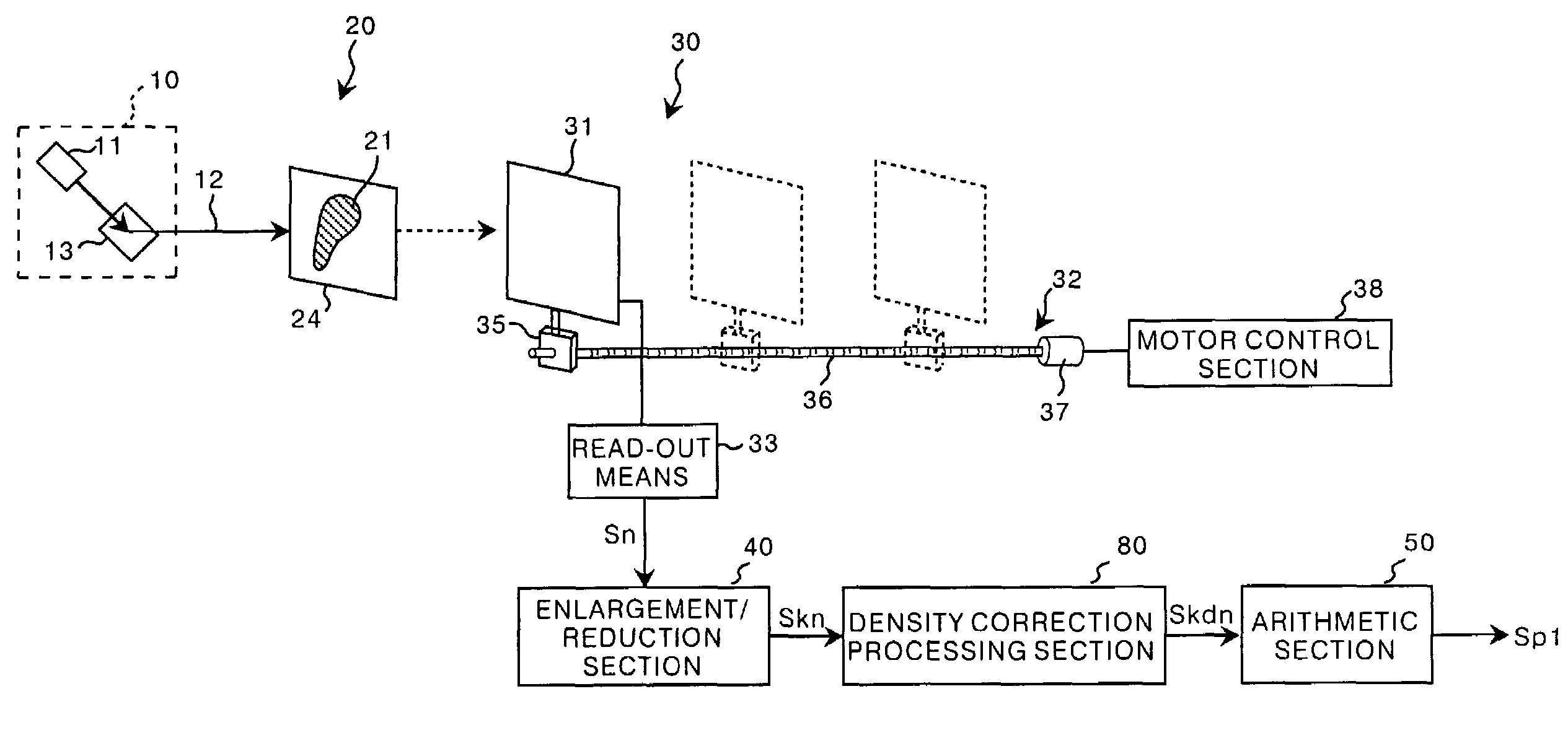
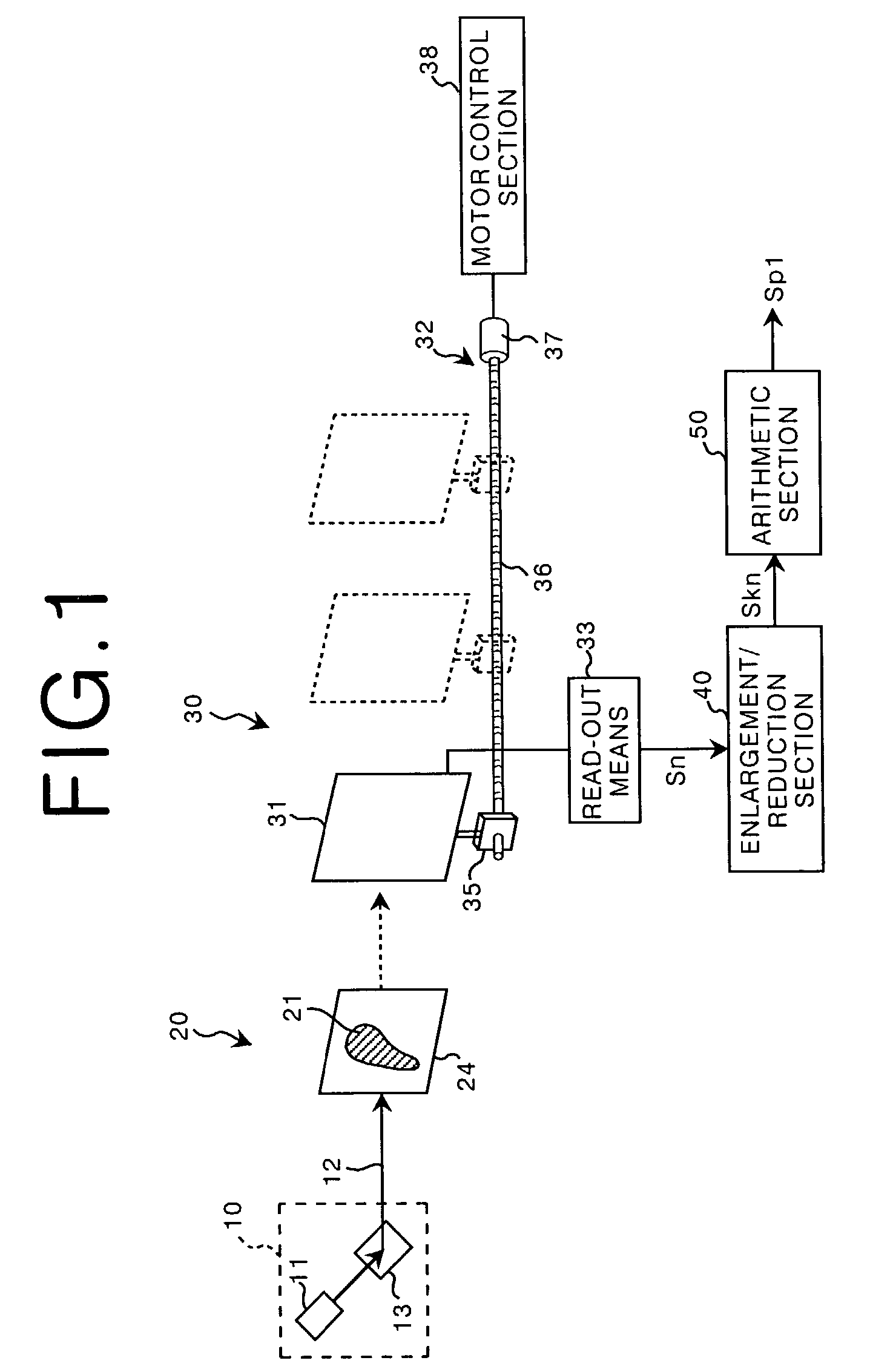
[0041]In FIG. 1, a phase contrast imaging apparatus in accordance with the present invention comprises an X-ray source section 10 which radiates an X-ray, an object support section 20 which supports an object 21, a recording section 30 which detects the X-ray passing through the object 21 at different distances from the object 21 and obtains a-plurality of pieces of image data Sn (n stands for 1 to N) representing a plurality of images of the object 21 taken at different distances, an enlargement / reduction processing section 40 which carries out an enlargement / reduction processing (to be described later) on the plurality of pieces of image data Sn and obtains a plurality of pieces of “size-matched” image data Skn and an arithmetic section 50 which obtains a phase contrast image data Sp1, representing a phase contrast image of the object 21, on the basis of the pieces of size-matched image data Skn.

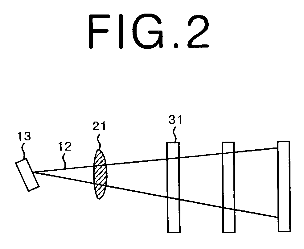
[0042]The X-ray source section 10 comprises a source 11 which emits a synchrotron radi...

second embodiment

[0061]The operation of the phase contrast imaging apparatus of the present invention will be described, hereinbelow, with reference to the flow chart shown in FIG. 6. The source 11 is driven to emit a synchrotron radiation and the synchrotron radiation is reflected by the crystal 13 and is converted into a monochromatic X-ray 12. The X-ray 12 is projected onto the object 21. (step S11) BY thus projecting the X-ray 12 onto the object 21, X-ray images of the object 21 are recorded on the respective stimulable phosphor sheets 61, 62 and 63 in the respective imaging positions. The read-out section 70 reads out the X-ray images from the stimulable phosphor sheets 61, 62 and 63 and obtains three pieces of image data Sn representing the X-ray images. (step S12)

[0062]The pieces of image data Sn obtained are input into the density correction processing section 80 and are subjected to the density correction processing, whereby a plurality of pieces of density-matched image data Sdn are obtain...

third embodiment

[0067]The operation of the phase contrast imaging apparatus of the present invention will be described, hereinbelow, with reference to the flow chart shown in FIG. 8. The source 11 is driven to emit a synchrotron radiation and the synchrotron radiation is reflected by the crystal 13 and is converted into a monochromatic X-ray 12. The X-ray 12 is projected onto the object 21. (step S21) Then the control section 38 drives the motor 37 to move the detector panel 31 away from the object 21 from the initial position nearest to the object 21. (step S22) As the detector panel 31 is moved, radiation images of the object 21 recorded on the detector panel 31 in the respective imaging positions as electric charges of the detecting elements of the detector panel 31 are read out by the read-out means 33 and a plurality of pieces of image data Sn representing the radiation images are obtained. (step S23).

[0068]The pieces of image data Sn obtained are input into the enlargement / reduction processin...


PUM

PropertyMeasurementUnit
phase contrastaaaaaaaaaa
distancesaaaaaaaaaa
sizesaaaaaaaaaa

Abstract

A phase contrast image is generated on the basis of a plurality of radiation images of an object taken in imaging positions which are different from each other in the distance from the object. An enlargement/reduction processing is carried out on the radiation images as taken in the imaging positions according to the distances between the imaging positions so that the radiation images become substantially the same in their sizes, and a phase contrast image is generated on the basis of the radiation images thus processed.

Description

BACKGROUND OF THE INVENTION[0001]1. Field of the Invention[0002]This invention relates to a method of and an apparatus for taking a plurality of radiation images at different distances from the object and generating a phase contrast image on the basis of the radiation images obtained.[0003]2. Description of the Related Art[0004]There has been known a radiation image reproduction system in which an object is exposed to a radiation (X-rays, α-rays, β-rays, electron beams, ultraviolet rays or the like), the radiation passing through the object is detected by the use of, for instance, a stimulable phosphor sheet (to be described later) or a radiation detector panel (to be described later), thereby obtaining a radiation image data representing a radiation image of the object, and a radiation image is reproduced on the basis of the radiation image data after it is variously processed.[0005]When certain kinds of phosphor are exposed to a radiation (X-rays, α-rays, β-rays, electron beams, u...

Claims


Application Information

Patent Timeline
Patent Type & Authority Patents(United States)
IPC IPC(8): G06K9/00A61B6/00G01N23/04G01T1/00G03B42/02G06T1/00G06T3/00G06T3/40G06T5/00G21K4/00H04N1/393H04N5/32
CPCA61B6/4216A61B6/484A61B6/502G01N23/04A61B6/4092G01N23/041
Inventor ITO, WATARU
Owner FUJIFILM CORP
Why Eureka
Try Eureka