Cleaning apparatus for a rotatable member

a cleaning apparatus and rotatable technology, applied in electrographic process apparatus, instruments, corona discharge, etc., can solve the problems of large amount of ozone, degrade image quality, and fouling the brush, and achieve the effect of increasing the efficiency of removal of fouling materials

Active Publication Date: 2008-03-18
SHARP KK
View PDF9 Cites 0 Cited by
  • Summary
  • Abstract
  • Description
  • Claims
  • Application Information

AI Technical Summary

Benefits of technology

[0015]According to the present invention, the elastic foam body with open cells that is pressed against by the rotatable member is provided. A large number of cell (bubble) holes are formed in the surface of this elastic foam body, and when the rotatable member presses against this elastic foam body, any developer or other fouling material adhering to the rotatable member is removed by the cell holes in the surface of the elastic foam body, and moreover the developer or other fouling material passes through the cells and is absorbed into the interior of the elastic foam body. Thus, developer or other fouling material adhering to the rotatable member is reliably removed, thus preventing uneven charging or damage to the electrostatic latent bearing members caused by developer or other fouling material adhering to the rotatable member. Furthermore, in the present invention, a cell wall removal ratio corresponding to a ratio of the open cells of the elastic foam body is set in accordance with a maintenance cycle. Here, the higher the cell wall removal ratio of the elastic foam body is, the higher the probability of connection between the cells of the elastic foam body is, so that developer or other fouling material can more quickly pass through the cells of the elastic foam body and even more developer or other fouling material can be absorbed. Accordingly, if the cell wall removal ratio of the elastic foam body is set to such a level that allows developer or other fouling material adhering to the rotatable member to be sufficiently absorbed during a single maintenance cycle, then the ability of the elastic foam body to absorb developer or other fouling material can be maintained until the time when maintenance is performed, thus making it possible to simplify the maintenance.
[0040]In this case, since the rotatable member contacts the bottom surface of the electrostatic latent bearing member, developer or other fouling material from the rotatable member does not go against the force of gravity and is removed by the cells of the elastic foam body, and thus developer or other fouling material passes through the cells and flows toward the discharge face, thereby increasing the efficiency of removal of fouling material.

Problems solved by technology

However, it also has a drawback in that it generates large amounts of ozone.
However, with the brush-contact type of charging apparatus, there is a drawback in that residual developer on the photosensitive drum or other fouling material may adhere to the brush, thus fouling the brush.
This fouling of the brush could cause uneven charging or damage to the photosensitive drum, thus leading to degraded image quality.
More specifically, the developer on the photosensitive drum cannot be transferred onto recording paper at 100% transfer efficiency, resulting in residual developer on the photosensitive drum.
However, increasing the pressing strength of the rubber blade would scrape the photosensitive layer of the photosensitive drum, and therefore, the pressing strength of this rubber blade cannot be sufficiently strong.
Accordingly, those components of the residual developer that have a small particle size, or those components of the residual developer that can form a strong electrostatic bond with the photosensitive drum cannot be removed, and the components of the residual developer on the photosensitive drum that have not been removed are absorbed electrostatically and caused to adhere to the brush of the charging apparatus.
However, in Patent Document 1, although developer adhering to the flocking of the rotatable member is removed by the brush cleaner, there is no description on the removal of the developer adhering to the brush cleaner.
Therefore, when the amount of the developer adhering to the brush cleaner increases, there is the possibility that the developer adhering to the brush cleaner may be reversely transferred to the rotatable member.
However, with this method, the electric field for removing the residual developer has a polarity opposite the polarity of charge of the photosensitive drum, producing an adverse effect on the charging characteristics of the photosensitive drum.
Moreover, such problems with rotatable members occur also with discharge brushes used to make contact with and discharge a photosensitive drum or the like, and cleaning brushes used to make contact with and clean a photosensitive drum or the like, causing uneven discharging and cleaning.
That is to say, developer or other fouling material adheres to the rotatable member, resulting in unevenness in the characteristics of the rotatable member.

Method used


Image

  • Cleaning apparatus for a rotatable member
  • Cleaning apparatus for a rotatable member
  • Cleaning apparatus for a rotatable member

Examples


embodiment 1

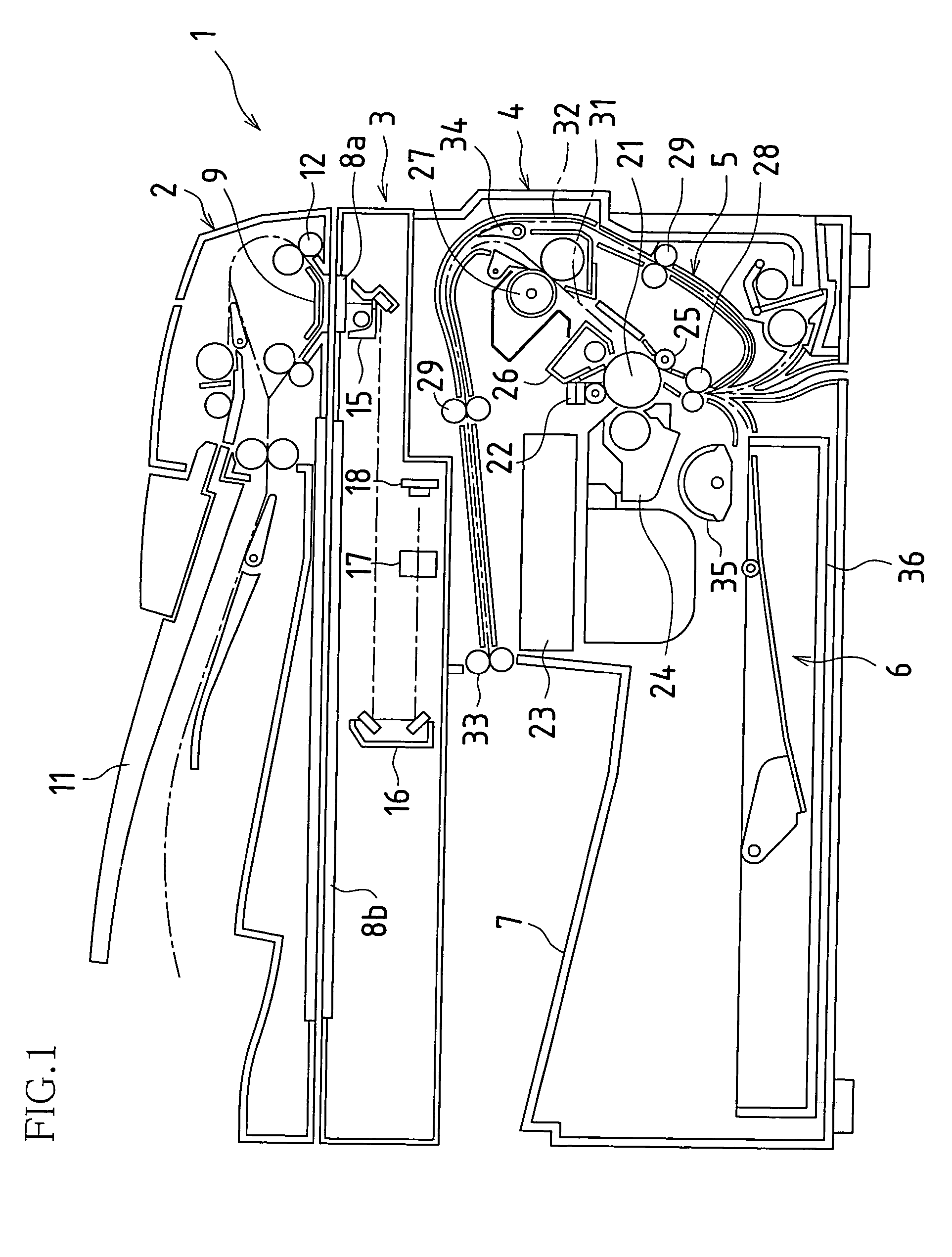
[0053]FIG. 1 is a side view showing an image forming apparatus to which the present invention is applied. This image forming apparatus 1 is provided with an original carrying unit 2, an original reading apparatus 3, a printing unit 4, a recording paper carrying unit 5, a paper-supply unit 6 and a paper-discharge tray 7.

[0054]In the original carrying unit. 2, when at least one original is loaded into an original loading tray 11, the originals are picked up and carried one sheet at a time from the original loading tray 11, and when the leading edge of an original reaches PS rollers 12, the carrying of the original is temporarily halted with the leading edge of the original brought parallel to the PS rollers 12. Then, after reaching synchronization with the image recording operation of the printing unit 4, a clutch between the PS rollers 12 and a driveshaft is engaged, driving the PS rollers 12 to rotate so that the original is again carried by the PS rollers 12 and the original is pas...

embodiment 2

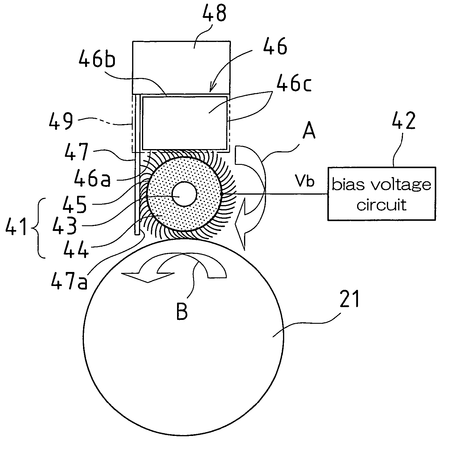
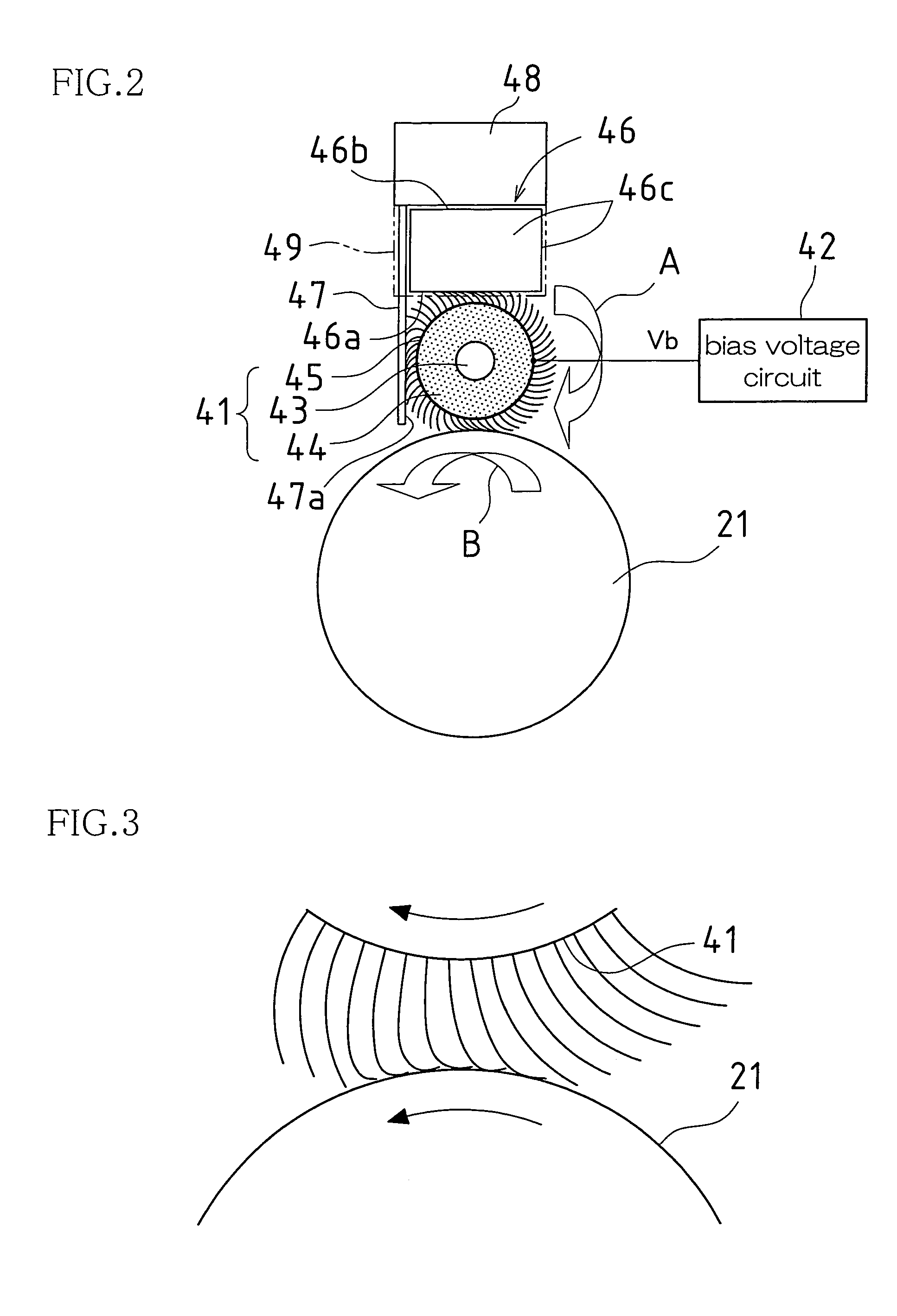
[0108]FIG. 10 is a schematic side view showing an image forming apparatus according to Embodiment 2 of the present invention. This image forming apparatus is used to form color images, being provided with four visible image forming units 60Y, 60M, 60C and 60B, and a transfer-fixing roller 61.

[0109]In each of the visible image forming units 60Y, 60M, 60C and 60B, a brush-based charging apparatus 22, a laser scan unit 63, a developing unit 64, a transfer roller 65 and a cleaner 66 are disposed around a photosensitive drum 62. The developing unit 64 of each of the visible image forming units 60Y, 60M, 60C and 60B contains toner of one of the colors yellow (Y), magenta (M), cyan (C) and black (B). Moreover, in the visible image forming units 60Y, 60M, 60C and 60B, once a uniform charge is applied to the surface of the photosensitive drum 62 by the brush-based charging apparatus 22, the laser beam of the laser scan unit 63 is modulated depending on the image information-while the laser b...


PUM


Abstract

The cell wall removal ratio of an elastic foam body is set such that developer or other fouling material adhering to a rotatable member can be continuously absorbed through the cells of the elastic foam body during a single maintenance cycle of an image forming apparatus. For example, the cell wall removal ratio of the elastic foam body is set to at least 60% or at least 80%. When the cell wall removal ratio of the elastic foam body is set to at least 60%, good image quality can be maintained reliably until the number of sheets recorded by the image forming apparatus reaches 20000. Furthermore, when the cell wall removal ratio of the elastic foam body is set to at least 80%, good image quality can be maintained reliably until the number of sheets recorded by the image forming apparatus reaches 30000.

Description

CROSS REFERENCE TO RELATED APPLICATIONS[0001]This application claims priority under 35 U.S.C. §119(a) on Patent Application No. 2004-157951 filed in Japan on May 27, 2004, and on Patent Application No. 2005-144210 filed in Japan on May 17, 2005, the entire contents of which are hereby incorporated by reference.BACKGROUND OF THE INVENTION[0002]The present invention relates to a cleaning apparatus for a rotatable member used in an electrophotographic image forming apparatus.[0003]In a known electrophotographic image forming apparatus, a photosensitive drum (an electrostatic latent bearing members) is rotated while a charging apparatus is used to apply a uniform electrostatic charge to the surface of the photosensitive drum, and a light beam is used to scan the surface of the photosensitive drum, thereby forming an electrostatic latent image on the photosensitive drum. A developer is applied to the electrostatic latent image upon the photosensitive drum, thus forming a development imag...

Claims


Application Information

Patent Timeline
Patent Type & Authority Patents(United States)
IPC IPC(8): G03G15/02
CPCG03G15/0258
Inventor TAKESAWA, YOICHIISHII, HIROSHI
Owner SHARP KK
Why Eureka
Try Eureka