Exhaust water trap

Active Publication Date: 2008-03-25
CUMMINS FILTRATION INC
View PDF21 Cites 18 Cited by
  • Summary
  • Abstract
  • Description
  • Claims
  • Application Information

AI Technical Summary

Benefits of technology

[0008]In one aspect, it is desired to move the water drainage hole from the side of a vertical muffler to the bottom or inlet end of the muffler. In one embodiment, this is accomplished by routing water past the catalytic converter or soot filter to the inlet side of the muffler where it pools and drains out of a drain hole in an inlet flange. The water is routed past the catalytic converter or soot filter substrate by utilizing a water trap design that incorporates a body inside of a body. The water travels past the substrate between the inner and outer bodies, thus eliminating leak paths that could exist which would allow exhaust gas to bypass the catalyst or particulate filter.
[0009]In the past, water and soot draining out of a side drain hole can leave black soot streaks and water marks on the side of the muffler. The water and soot mixture may also corrode brac

Problems solved by technology

In another scenario, freezing of water in the catalytic converter can cause structural damage to the monolithic catalyst.
As an additional problem, water flowing through the catalytic converter or soot filter may tend to wash particulate material downwardly where such material collects and clogs the lower surface of the catalytic converter/soot filter causing

Method used


Image

  • Exhaust water trap
  • Exhaust water trap
  • Exhaust water trap

Examples


Embodiment Construction

Parent Applications

[0020]The following description of FIGS. 1 and 2 is taken from the noted parent applications.

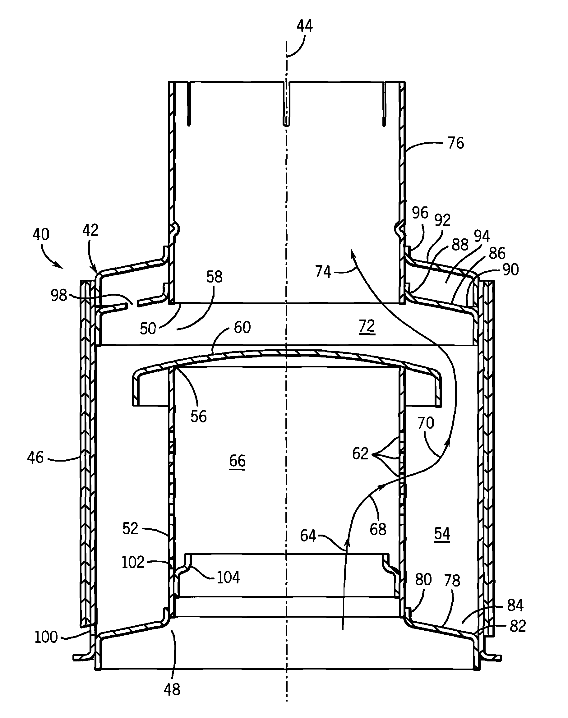
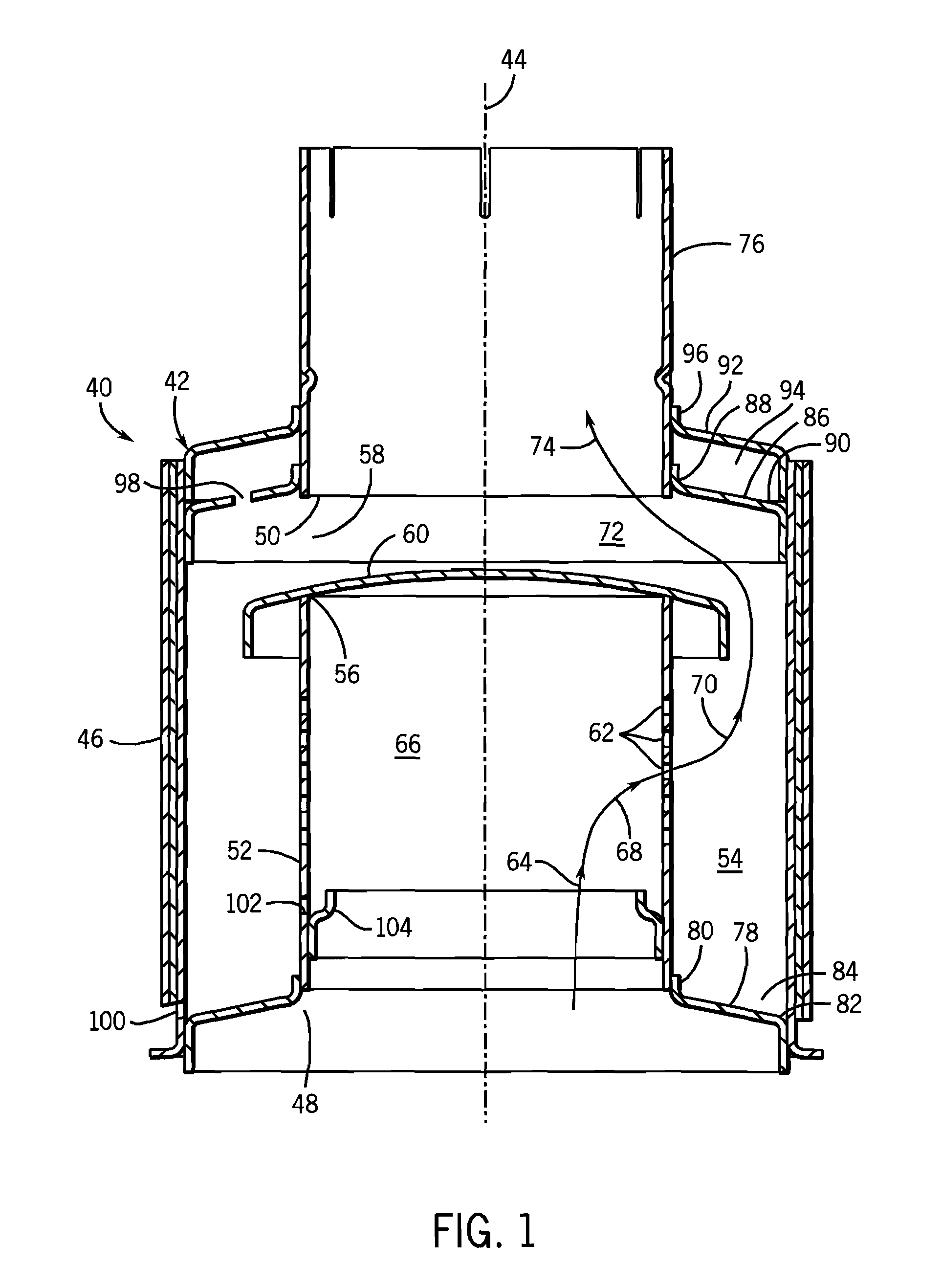
[0021]FIG. 1 shows an exhaust water trap assembly 40 including a housing 42 extending axially along a vertical axis 44 and having a housing sidewall 46. The housing has a lower inlet 48 for receiving exhaust from an internal combustion engine through a catalytic converter or soot filter, and an upper outlet 50 for discharging the exhaust and which is spaced above lower inlet 48. An internal exhaust tube 52 extends upwardly from lower inlet 48 and is spaced radially inwardly of housing sidewall 46 by a radial gap defining an annular space 54 therebetween. Exhaust tube 52 has a top end 56 vertically spaced below upper outlet 50 by an axial gap 58. A dome cap or umbrella 60 on top end 56 spans internal exhaust tube 52 and blocks exhaust flow axially upwardly therepast, and blocks entry of water axially downwardly therepast into top end 56 of internal exhaust tube 52 from uppe...


PUM


Abstract

A vertical exhaust water trap assembly has an outer housing and an internal housing or exhaust tube defining an annular water collection spaced therebetween bypassing a central exhaust flow area.

Description

CROSS-REFERENCE TO RELATED APPLICATIONS[0001]This application is a continuation-in-part of U.S. patent application Ser. No. 11 / 085,715, filed Mar. 21, 2005 now U.S. Pat. No. 7,114,330, which is a continuation of Ser. No. 10 / 376,424 filed Feb. 28, 2003 U.S. Pat. No. 6,868,670.BACKGROUND AND SUMMARY[0002]The invention relates to vertical exhaust systems and exhaust water trap assemblies, including for heavy duty vehicles, such as trucks, tractors, off-road equipment, and the like which utilize a vertical exhaust system, for example in which the exhaust conduit extends vertically alongside the cab of the vehicle.Parent Applications[0003]For reduced emissions, catalytic converters and soot filters have been incorporated in the exhaust system of buses, trucks, and so on. If the exhaust outlet is vertical, there is a possibility that water, such as rain, snow, or bus or truck wash, can enter the upper end of the exhaust system and flow downwardly into contact with the catalytic converter ...

Claims


Application Information

Patent Timeline
IPC IPC(8): F01N3/02F02B27/02
CPCF01N1/04F01N1/083F01N3/005F01N3/021F01N3/20F01N2230/02F01N2230/04Y02T10/20F01N2590/08Y02T10/12
Inventor LUBENOW, SCOTT M.KLEIN, PATRICK M.SCHELLIN, ROBERT J.
Owner CUMMINS FILTRATION INC
Why Eureka
Try Eureka