Controller and controlling method for internal combustion engine

a technology of internal combustion engine and control method, which is applied in the direction of electric control, speed sensing governor, speed sensing device, etc., can solve the problems of affecting the acceleration/deceleration of the vehicle, the torque which can be guaranteed by correcting the ignition timing, and the intake system response delay

Active Publication Date: 2008-03-25
DENSO CORP
View PDF9 Cites 17 Cited by
  • Summary
  • Abstract
  • Description
  • Claims
  • Application Information

AI Technical Summary

Benefits of technology

[0010]The present invention is made in view of the foregoing matter and it is an object of the present invention to provide an engine controller and engine control method which can restrict fluctuation in engine speed and / or unintentional acceleration / deceleration when driving torque of components are rapidly changed.

Problems solved by technology

Generally, since the engine torque is controlled based on a throttle position (intake air amount) or a fuel injection amount, a response delay exists in an intake system.
However, the torque which can be ensured by correcting the ignition timing is limited.
Thereby, when the driving torque of components are rapidly changed, even if both intake air amount and ignition timing are corrected, the torque correction amount runs shortage relative to the rapid change in driving torque of the components, which may cause the fluctuation in engine speed and the acceleration / deceleration of the vehicle.
However, the estimated value of the increased / decreased amount of driving torque of the components must includes some errors due to a individual productive dispersion or an aging thereof.
Furthermore, the engine torque command value may be deviated from the actual engine torque due to such a dispersion and aging.
Even if the increased amount (decreased amount) of the driving torque of the components and the increased amount (decreased amount) of the engine torque are controlled in synchronization with each other, the torque error cannot be avoided.
The above fluctuation in engine speed and unintentional acceleration / deceleration cannot be restricted enough.

Method used


Image

  • Controller and controlling method for internal combustion engine
  • Controller and controlling method for internal combustion engine
  • Controller and controlling method for internal combustion engine

Examples


first embodiment

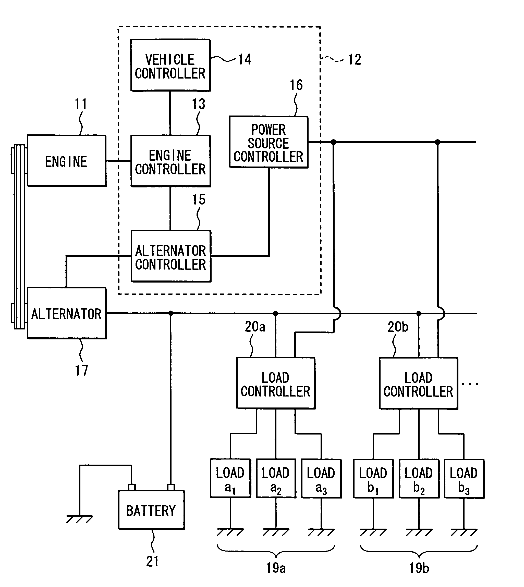
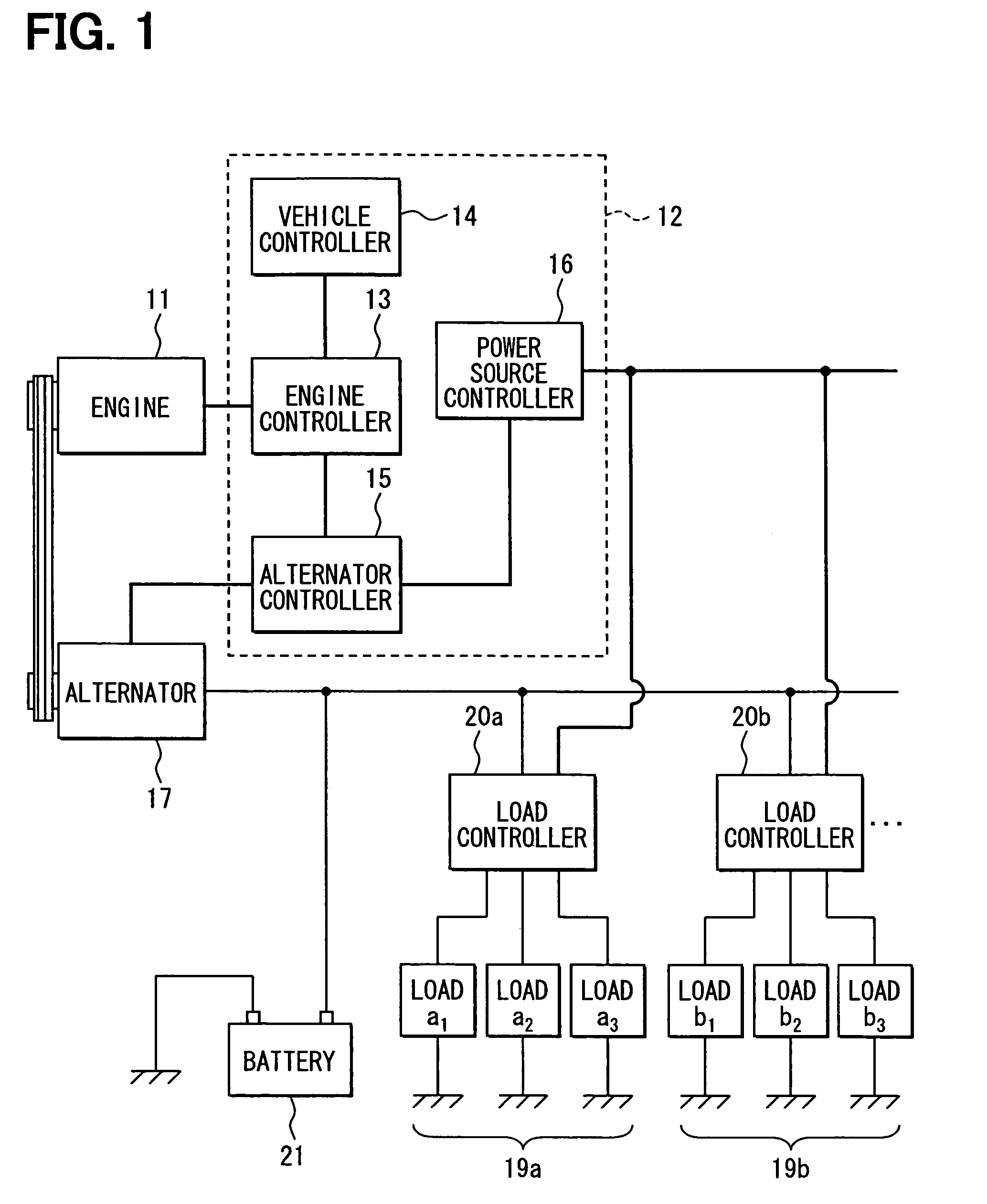
[0026]FIG. 1 is a schematic view showing an engine control system. Each device of air system, fuel injection system and ignition system of an engine 11 is controlled by an engine controller 13 which is included in a controlling apparatus 12. The controlling apparatus 12 includes a vehicle controller 14, an alternator controller 15, and a power source controller 16. These controllers are electrically connected with each other.

[0027]The vehicle controller 14 calculates a required vehicle driving torque, which represents an engine torque necessary for driving the vehicle. A signal indicative of the required vehicle driving torque is transmitted to the engine controller 13.

[0028]The alternator controller 15 controls electric current generated by an alternator 17 by controlling electric current applied to filed coils of the alternator 17 based on a permitted power generation torque (permitted components driving torque)

[0029]The power source controller 16 is electrically connected to the ...

second embodiment

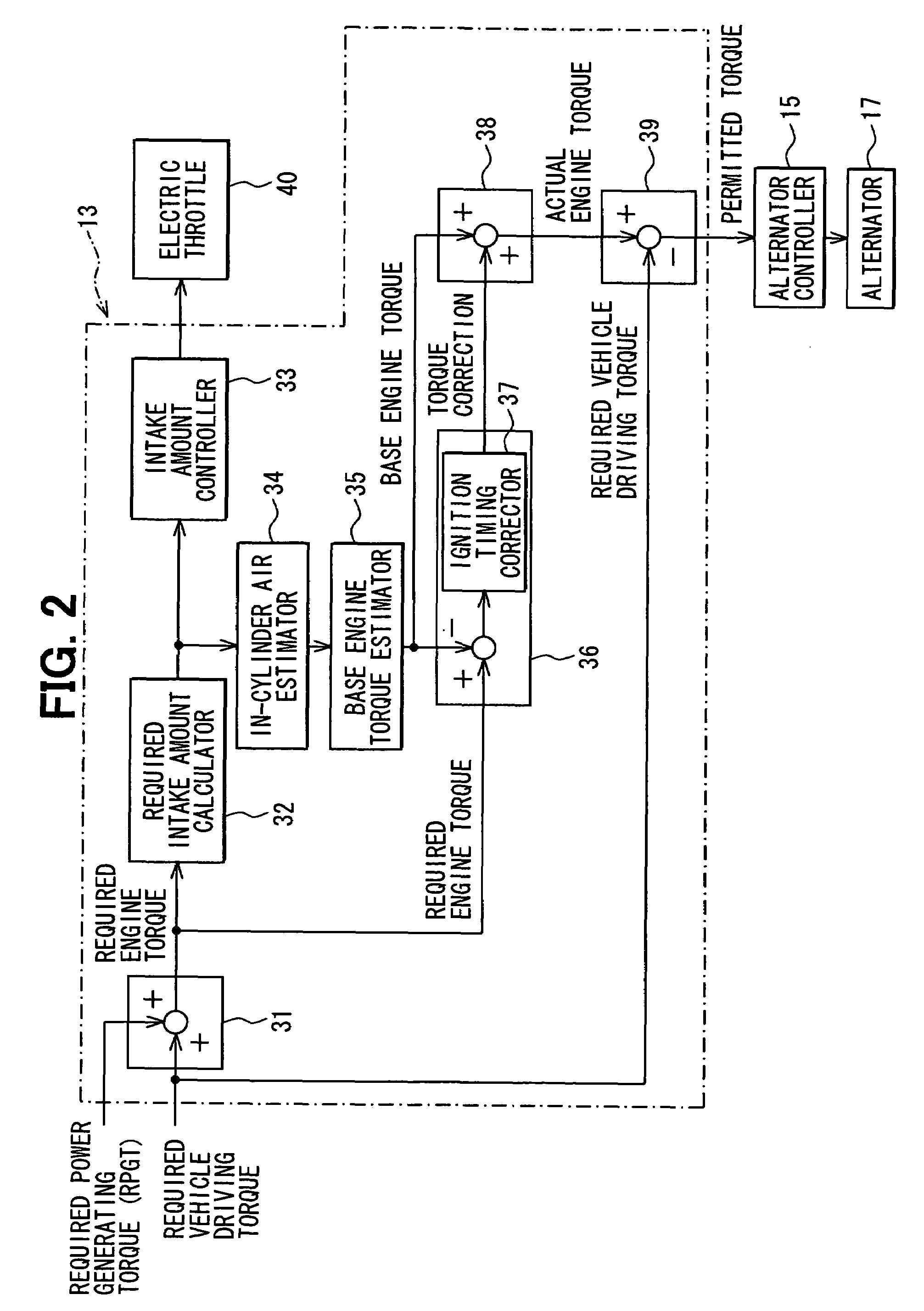
[0050]In a case of a direct injection engine, the engine torque can be corrected by correcting the fuel injection amount. Referring to FIG. 2, a second embodiment will be described hereinafter.

[0051]A torque corrector 36a corrects the fuel injection amount by use of a fuel injection amount corrector 37a based on a difference between the required engine torque and the base engine torque. The torque corrector 36a calculates the torque correction amount based on the correction amount of the fuel injection amount. An actual engine torque estimator 38 estimates the actual engine torque which can be realized in the next calculation timing by adding the torque correction amount to the base engine torque. A permitted power generation torque calculator 39 calculates a difference between the actual engine torque and the required vehicle driving torque. This difference corresponds to the permitted power generation torque. The alternator 17 is driven with this permitted power generation torque....

third embodiment

[0055]Referring to FIG. 6, a third embodiment will be described hereinafter. In the third embodiment, the same parts and components as those in the first embodiment are indicated with the same reference numerals and the same descriptions will not be reiterated.

[0056]The engine controller 13 includes a torque corrector 18, which corrects control error of the engine torque. The engine controller 13 and the alternator controller 15 function as a torque correction amount learning unit 22. When a torque correction amount learning condition is established, the unit 22 changes torque, which is necessary to drive the alternator 17, by control current and learns the torque correction amount corrected by the torque corrector 18. This learn-value is stored in a backup RAM 23. The engine controller 13 corrects a torque command value transmitted from the vehicle controller 14 based on the learn-value, and controls the engine torque.

[0057]When the driving torque of the alternator 17 is rapidly ch...


PUM


Abstract

A base engine torque generated with an estimated intake air amount is estimated. An engine torque is corrected by correcting an ignition timing based on a difference between a required engine torque and the base engine torque. A torque correction amount is calculated based on a correction amount of the ignition timing. An actual engine torque is estimated based on the calculated torque correction amount and the base engine torque. A permitted component driving torque is a difference between the actual engine torque and the required vehicle driving torque. A component is controlled based on the permitted component driving torque.

Description

CROSS REFERENCE TO RELATED APPLICATIONS[0001]This application is based on Japanese Patent Applications No. 2005-317844 filed on Nov. 1, 2005, and No. 2005-336470 filed on Nov. 22, 2005, the disclosure of which are incorporated herein by reference.FIELD OF THE INVENTION[0002]The present invention relates to a controller for an internal combustion engine, and a controlling method for an internal combustion engine. The internal combustion engine is provided with function in which driving torque of components, which is driven by an engine torque, is controlled. The engine torque represents an output torque of the engine.BACKGROUND OF THE INVENTION[0003]A vehicle is equipped with components which are driven by engine. For example, the engine is equipped with an alternator, a compressor for air conditioner, a high-pressure pump for increasing fuel pressure, an oil pump, a motor generator, and the like. Since, these components are driven by the engine, a fluctuation in engine speed and / or ...

Claims


Application Information

Patent Timeline
Patent Type & Authority Patents(United States)
IPC IPC(8): F02M1/00F02D41/00
CPCF02P5/103B60W10/06B60W10/08B60W10/30B60W30/1886F02D41/1497F02D41/182F02D2200/1004F02D2200/503B60W2710/0666F02D41/2451F02D2200/1002Y02T10/42Y02T10/40
Inventor KURODA, DAISUKEYAMASHITA, YUKIHIROTANI, KEISUKEOBAYASHI, KAZUYOSHITANAKA, KATSUNORI
Owner DENSO CORP
Why Eureka
Try Eureka