
Anesthesia apparatus with remote control during operation in a manual ventilation mode

Active Publication Date: 2008-03-25
MAQUET CRITICAL CARE
View PDF10 Cites 33 Cited by
  • Summary
  • Abstract
  • Description
  • Claims
  • Application Information

AI Technical Summary

Benefits of technology

[0010]With a remote control for the more important functions of manual ventilation the operator is able to maintain undivided attention on the patient while the parameters are being changed by the remote operation of the user interface. The remote control and the user interface are adapted so that the remote control can be used only during manual ventilation. Thus, during mechanical ventilation the remote control cannot affect the installed settings, which means that no unintentional changes can be made during mechanical ventilation.
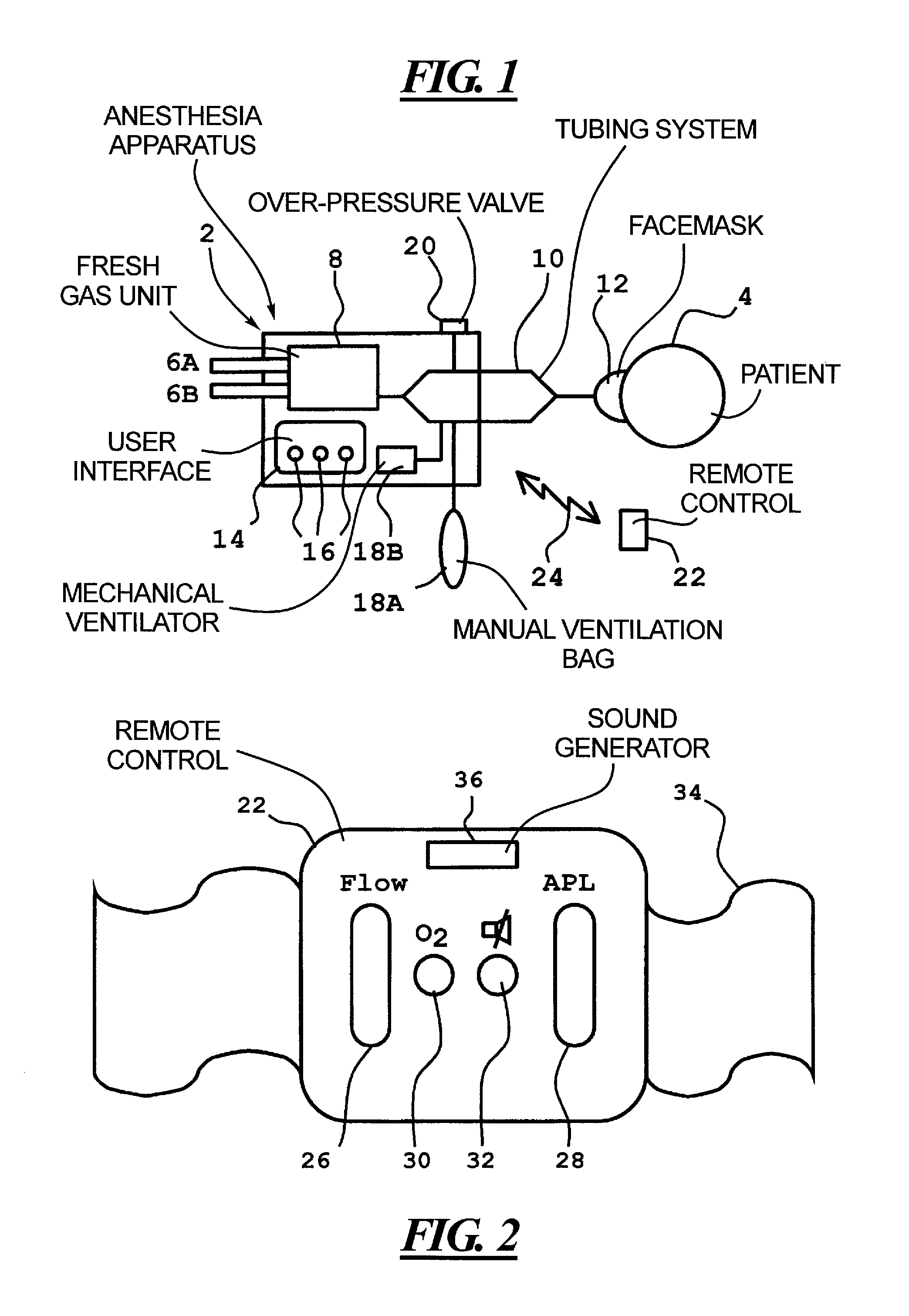
[0011]In this connection, it is an advantage for the remote control to include controls for the regulation of fresh gas flow and permitted over-pressure level, these being the more important machine parameters for manual ventilation. The controls may, to this end, be realized as a wheel (analogous to a computer mouse wheel) but with a distinct position related to a predetermined setting of the parameters. These parameters may be permanently programmed for the device, or may be programmable for every patient, or may be values that are programmed by the operator for use when manual ventilation is switched in. With the last-mentioned alternative, the wheel can be made to automatically occupy this distinct position as soon as manual ventilation is switched in. This may be easily achieved using a control signal from the user interface to the remote control and a small drive motor for the wheel responsive to this signal.
[0012]Moreover, the remote control may include push-buttons for oxygen flushing and alarm shut-off. When the above-described wheels are used as the controls they may also be provided with a push-button functionality for the oxygen flushing and the alarm shut-off. In this way the remote control may be made small, lightweight and easy to use.

Problems solved by technology

A problem with this conventional technique is that in order to make changes to the entered parameters, the anesthesiologist is forced to divert his or her attention from the patient during the time it takes to make the changes via the user interface.

Method used


Image

  • Anesthesia apparatus with remote control during operation in a manual ventilation mode
  • Anesthesia apparatus with remote control during operation in a manual ventilation mode

Examples


Embodiment Construction

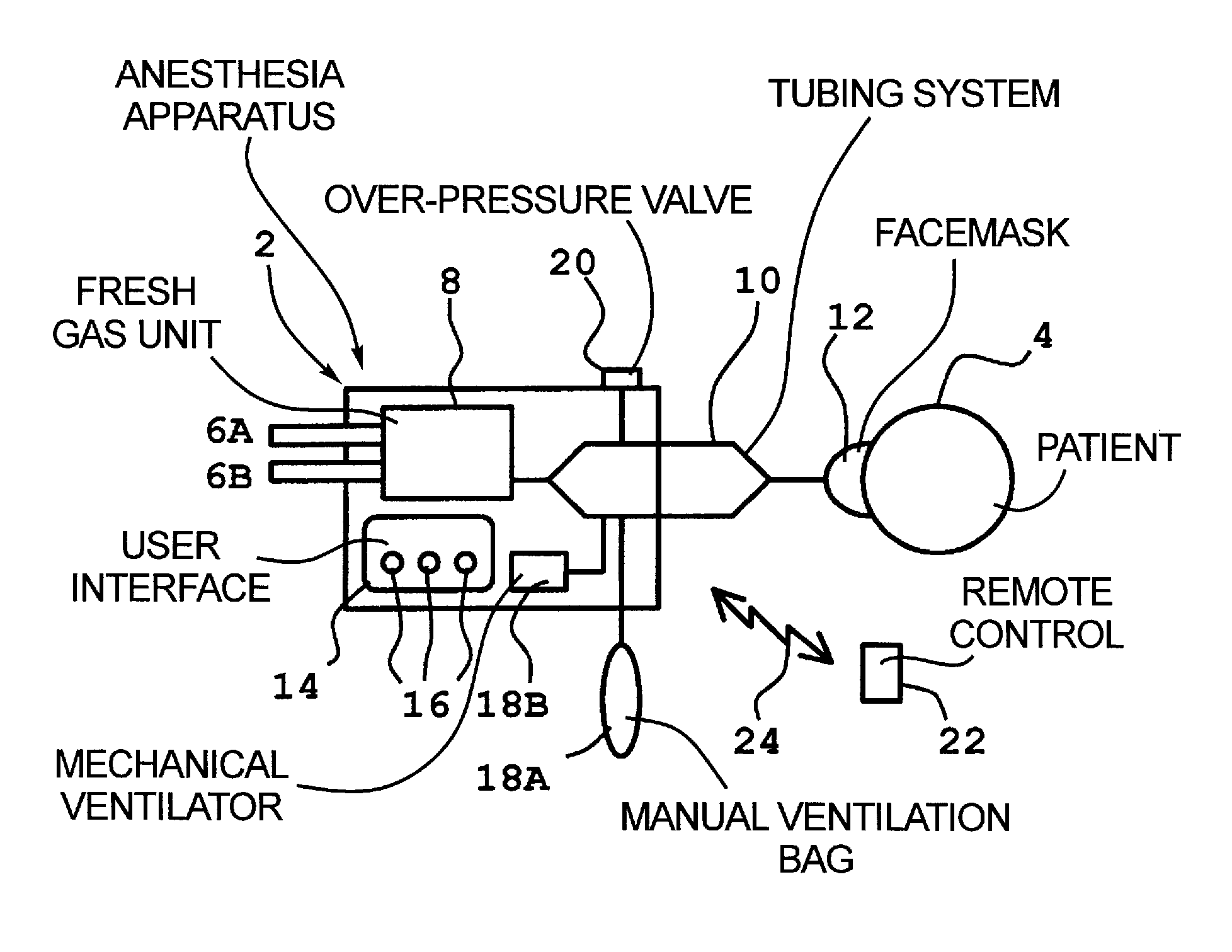
[0017]An anaesthesia apparatus 2 according to the invention is shown schematically in FIG. 1. The anaesthetic device is connected to a patient 4 to be anaesthetized.

[0018]Some of the components for the preparation of fresh gas in the anaesthesia apparatus 2 are a first gas connection 6A for nitrous oxide; a second gas connection 6B for oxygen; and a fresh gas unit 8 for the blending of a chosen mixture of nitrous oxide and oxygen and possibly even for supply of an anaesthetic agent.

[0019]Other arrangements for the preparation of fresh gas are known and the anaesthesia apparatus 2 may equally as well include one or more of these.

[0020]The fresh gas is conducted via a tubing system 10 to a facemask 12 that is placed over the mouth and nose of the patient 4. It should be noted that several different tubing systems are used in the field of anaesthesiology, for example an open system without re-breathing; a half-open system such as Bain and Mapelson with partial re-breathing; and a close...


PUM


Abstract

An anaesthetic device has a manual ventilation bag, a mechanical ventilator and a user interface for setting an operating mode, including mechanical ventilation via the mechanical ventilator and manual ventilation via the manual ventilation bag, and for setting parameter values for the operating mode that has been set. The anaesthetic device further has a remote control for wireless transmission of commands to the user interface. The user interface is adapted to carry out the commands from the remote control only when the anaesthetic device is set for manual ventilation.

Description

BACKGROUND OF THE INVENTION[0001]1. Field of the Invention[0002]The present invention relates to an anaesthesia apparatus of the type having a manual ventilation bag, a mechanical ventilator, and a user interface for selecting an operating mode of the apparatus.[0003]2. Description of the Prior Art[0004]Anaesthesia apparatuses generally are designed to operate in many different operating modes. Two of these are manual ventilation, in which the anaesthetist controls / supports the breathing of a patient by means of a manual ventilation bag, and mechanical ventilation, in which the breathing of the patient is controlled / supported by means of a mechanical ventilator (the mechanical ventilation may itself be divided in to a number of sub-modes such as pressure regulation, volume regulation, etc.).[0005]The set-up of an operating mode generally is done via a user interface (which itself may include several components located at different parts of the anaesthetic device). Parametric values ...

Claims


Application Information

Patent Timeline
IPC IPC(8): A61M11/00A61M16/00A61M16/12A61M16/01A61M16/10
CPCA61M16/0051A61M16/01A61M16/1015A61M16/0078A61M2205/3569A61M2205/3592A61M16/021A61M2205/502
Inventor AHLMEN, CHRISTERLONCAR, MARIOVIDEBRINK, PETTER
Owner MAQUET CRITICAL CARE
Learn More