Self regulating spout

a self-regulating, spout technology, applied in the direction of liquid dispensing, drinking vessels, applications, etc., to achieve the effect of reducing vacuum and making fluid extraction easy

Inactive Publication Date: 2008-04-01
ESSEBAGGERS JAN
View PDF19 Cites 18 Cited by
  • Summary
  • Abstract
  • Description
  • Claims
  • Application Information

AI Technical Summary

Benefits of technology

[0008]The present invention overcomes the latter problem by inverting the membrane, which now pushes the valve open rather than pulling, thereby combining a number of advantages over prior art solutions. This means that the spring stiffness has no relation with the internal gas pressure of the container and for that matter a very weak spring can be used, just adequate to pull the valve closed. If the gas pressure increases, the valve will be pushed onto it...

Problems solved by technology

A small suction pressure difference over the inverted membrane will result in a relative large force to open t...

Method used


Image

  • Self regulating spout
  • Self regulating spout
  • Self regulating spout

Examples


first embodiment

[0020]In FIGS. 3-a through 3-i (in which FIG. 3-d is a top view of blade spring FIG. 3-e) the individual parts are drawn that makes up the SRS as described above of the first preferred embodiment. This first embodiment of the SRS, which can be disassembled for cleaning, is not meant to limit the invention to other configurations or be only used for carbonized beverages. Other configurations are conceivable, whereby the same principle of force enlargement is applied by using an inverted perforated membrane that activates a valve, against the inside pressure of the bottle or fluid container.

[0021]In FIGS. 5 and 6 a second preferred embodiment is shown, depicting a longitudinal cross section and a top view of the SRS respectively for use with a disposable bottle, whereby the SRS is assembled in such away that it cannot be taken apart for cleaning and is for one time use only, hereafter further identified as SRS 2′. As the principle of operation of the SRS 2′ for this application, is ex...

second embodiment

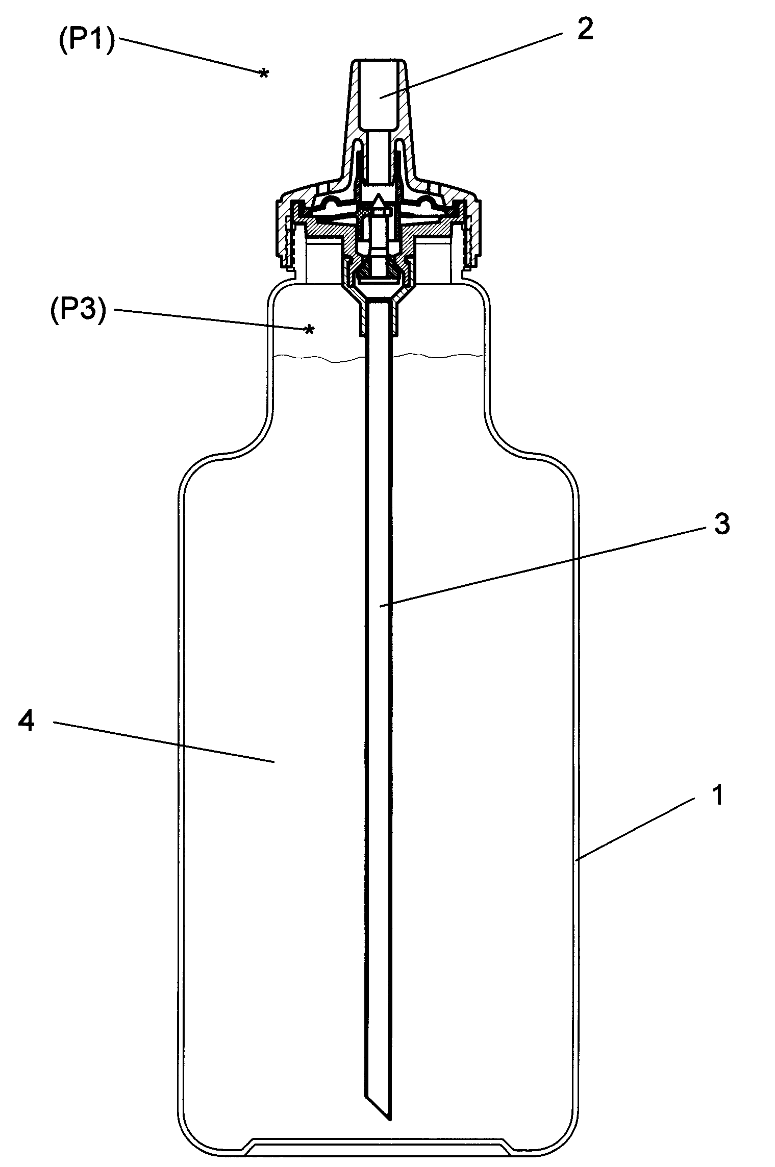
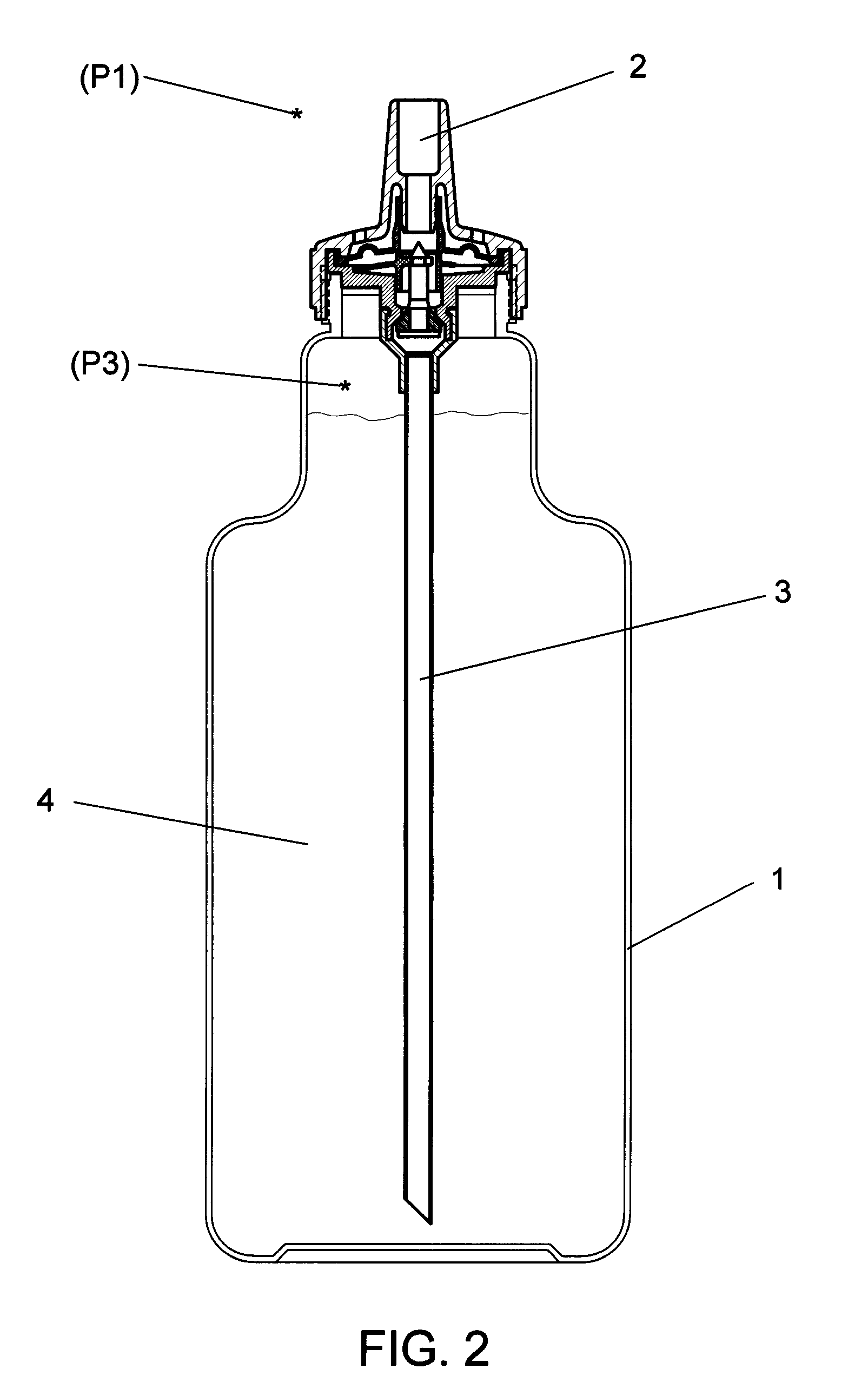
[0023]The SRS 2′ assembly, being the invention, comprising a spout 7′ and a valve housing 5′ in which the inverted membrane 8′ and valve assembly 12′, 13′ and 24′ are held, is gas tight connected with a screw cap 26′ to the bottle neck 21′ of bottle 1′ by means of a screw thread connection 20′.

[0024]The prime difference between the two described embodiments of the invention is that the separate blade spring 16 of FIG. 3 for closing the valve has been eliminated and that the valve thereby is closed by the inverted membrane itself, as depicted in FIG. 5.

[0025]The thus described embodiments require a gas tight sliding seal between the extruded tube 9 (9′) of the inverted membrane 8 (8′) with a seal 10 (10′) sliding over the extruded inner tube / (spigot) 11 (11′) within the spout 7 (7′) and thus forming a siding seal. Air leakage at this location could cause the SRS to malfunction. This, however, will never result in a leakage of the fluid or gas from the bottle or container to the outsi...


PUM


Abstract

A drinking spout for beverage cans, bottles, cups or handheld containers that temporarily hold a drinking fluid (beverage), which can be carbonated or a hot drink under pressure and which is closed off by the spout. Spilling of the fluid held therein is prevented during awkward drinking situations such as in cars while driving, walking or other less controlled drinking conditions. The fluid in the container, remains under pressure while permanent access is possible through the spout. The spout comprises a suction piece that is leak tight attached to a valve housing which holds a spring, a centrally perforated inverted membrane and a valve. When suction is applied to the spout, the inverted membrane moves downwards thereby opening the valve against the internal pressure of the bottle or container and allowing fluid to pass to the mouth. When the suction stops, a spring closes the valve. Air venting is provided, through the same valve, when the internal gas pressure drops below the atmospheric pressure.

Description

FIELD OF THE INVENTION[0001]The invention is used as a means to empty by mouth beverage cans, bottles or drinking cups with cover, or other hand held containers, used for storing temporarily a carbonized or non-carbonized drinking fluid. The invention enables the extraction of the fluid without spilling, while in action and fluid is withdrawn from the handheld container or when the container is overturned. U.S. class 220 / 706; 220 / 85; 222 / 214; 220 / 713; 220 / 714 etc. (International Patent Classification A47G19 / 22; BD65d 1 / 00; BD65D 25 / 48 etc.) This patent is an improvement over a former patent published under U.S. Pat. No. 6,290,090 as referenced in the “Information Disclosure Statement” (IDS) to this application, thereby providing a new inventive disclosure, not foreseen in U.S. Pat. No. 6,290,090.OBJECT OF THE INVENTION[0002]Carbonated beverages are supplied in aluminum cans, bottles or other containers for consumption. As soon as the can or bottle is opened, the fluid starts deterio...

Claims


Application Information

Patent Timeline
IPC IPC(8): A47G19/22B67D3/00
CPCA47G19/2272
Inventor ESSEBAGGERS, JAN
Owner ESSEBAGGERS JAN
Why Eureka
Try Eureka