Structure of scroll of variable-throat exhaust turbocharger and method for manufacturing the turbocharger

a variable-throat exhaust and scroll technology, which is applied in the direction of positive displacement liquid engines, piston pumps, and ways, can solve the problems of increased manufacturing costs, poor productivity, and increased manufacturing costs, so as to increase the capacity of the exhaust turbine, increase the cross sectional area, and increase the size of the turbine casing

Active Publication Date: 2008-04-01
MITSUBISHI HEAVY IND ENGINE & TURBOCHARGER LTD
View PDF13 Cites 29 Cited by
  • Summary
  • Abstract
  • Description
  • Claims
  • Application Information

AI Technical Summary

Benefits of technology

[0016]The object of the present invention is to provide a variable-throat exhaust turbocharger increased in exhaust turbine capacity by increasing the A / R, the ratio of cross sectional area A of a scroll passage to a scroll radius R, without increasing the size of the turbine casing and with very simple construction. The turbocharger can then be increased in efficiency and the engine output can be increased.

Problems solved by technology

When intending to decrease scroll radius R, it is needed to displace the scroll chamber radially inwardly, but it is difficult because there is, in the radially inner side of the scroll chamber, an annular flow passage in which the nozzle vanes are located.
It is proposed to widen the scroll chamber largely axially inwardly to increase the A / R ratio, but in that case, manufacturing of the core for forming the scroll chamber when casting is more difficult and productivity is poor.
However, it is inevitable that the manufacturing cost increases due to the additional processing.

Method used


Image

  • Structure of scroll of variable-throat exhaust turbocharger and method for manufacturing the turbocharger
  • Structure of scroll of variable-throat exhaust turbocharger and method for manufacturing the turbocharger
  • Structure of scroll of variable-throat exhaust turbocharger and method for manufacturing the turbocharger

Examples


first embodiment

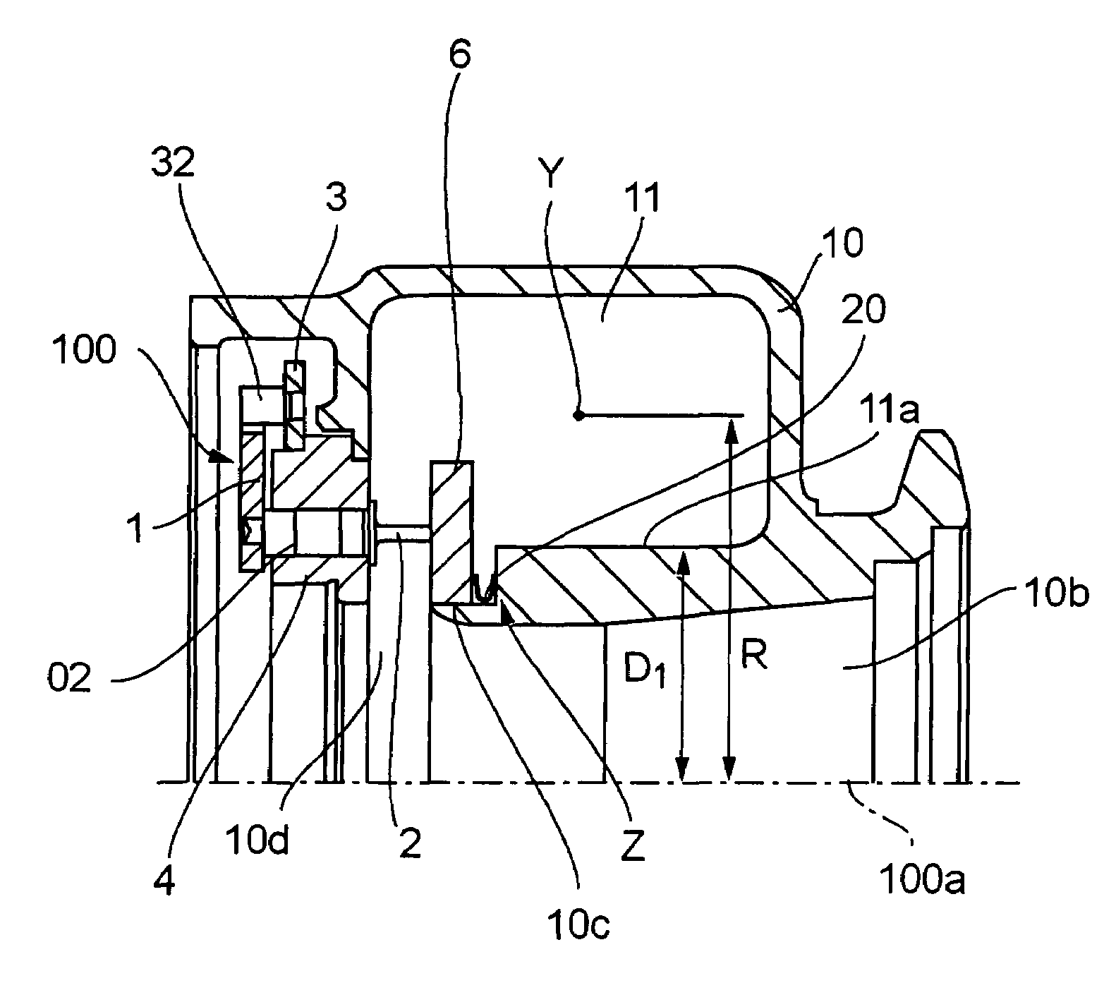
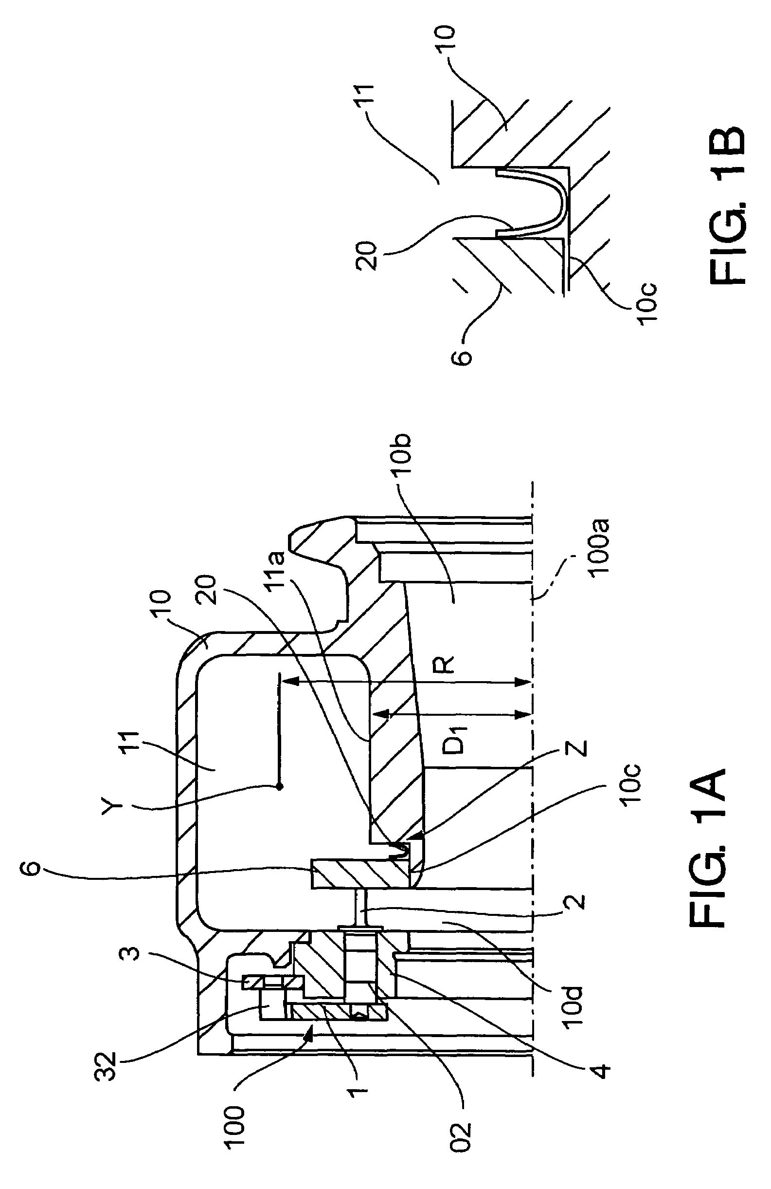
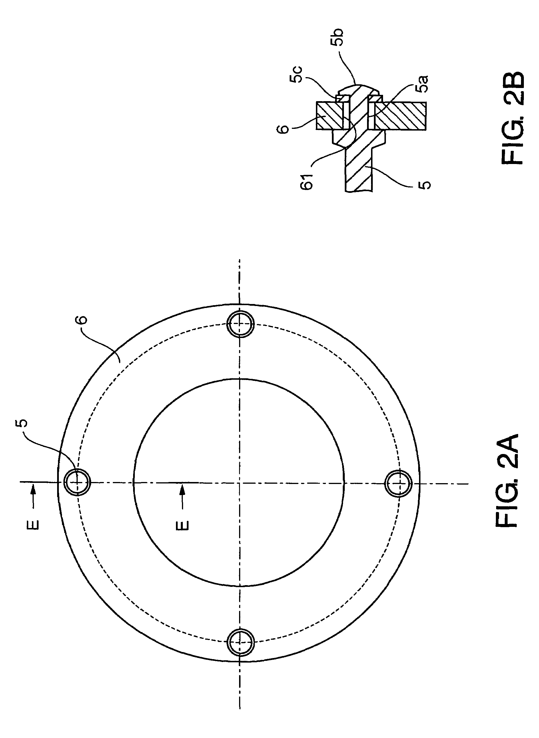
[0063]FIG. 1A is a longitudinal sectional view of relevant part of a variable-throat exhaust turbocharger equipped with a variable-throat mechanism of the first embodiment according to the present invention, and FIG. 2A and FIG. 2B are representations showing connection of the nozzle plate and nozzle supports of the first embodiment, FIG. 2A is a front view, and FIG. 2B is a sectional view taken along line E-E in FIG. 2A.

[0064]Referring to FIG. 1A, reference numeral 10 is a turbine casing and 11 is a scroll chamber formed inside the turbine casing 10. Reference numeral 100a is the center of rotation of the exhaust turbocharger, the turbine rotor 12 of which (see FIG. 8) is omitted in the drawing.

[0065]Reference numeral 2 is a nozzle vane. Plural nozzle vanes are arranged circumferentially equally spaced in an annular flow passage formed on the inner side of the scroll chamber 11. A nozzle shaft 02 of each of the nozzle vanes is supported rotatably by a nozzle mount 4 fixed to the tu...

second embodiment

[0079]FIG. 3 is a drawing of a second embodiment corresponding to FIG. 1.

[0080]In the second embodiment, the periphery of the nozzle plate 6 is tapered toward the entrance of the annular flow passage 10e where the nozzle vanes 2 are arranged. By this, an exhaust gas guide portion 6a is formed by which the exhaust gas flow area is smoothly decreased from the scroll chamber 11 to the annular flow passage 10e at the entrance thereof.

[0081]The configuration other than that is the same as that of the first embodiment, and parts the same as the first embodiment are designated by the same reference numerals.

third embodiment

[0082]FIG. 4 is a drawing of the third embodiment corresponding to FIG. 1.

[0083]In the third embodiment, the periphery of the nozzle plate 6 is rounded facing the entrance of the annular flow passage 10e where the nozzle vanes 2 are arranged. By this, an exhaust gas guide portion 6b is formed by which exhaust gas flow area is smoothly decreased from the scroll chamber 11 to the annular flow passage 10e at the entrance thereof.

[0084]The configuration other than that is the same as that of the first embodiment and parts the same as the first embodiment are designated by the same reference numerals.

[0085]According to the second and third embodiments, by providing a tapered portion (in the second embodiment) or rounded portion (in the third embodiment) at the periphery of the nozzle plate 6 to face the entrance of the annular flow passage 10e so that exhaust gas guide portion 6a (in the second embodiment) or 6b (in the third embodiment) is formed by which exhaust gas flow area is smooth...


PUM


Abstract

A ratio of cross sectional area A of a scroll passage to a scroll radius R (A / R) can be increased without increasing the size of a turbine casing and with very simple construction. An exhaust turbine capacity can thus be increased, so that a variable-throat exhaust turbocharger in which the engine output can be increased results. The turbocharger has a nozzle throat area varying mechanism of which a nozzle assembly unit is composed. A plurality of nozzle vanes are supported rotatably by an annular nozzle mount and an annular nozzle plate is connected to the nozzle mount by a plurality of nozzle supports to sandwich the nozzle vanes. The nozzle plate is located in the scroll chamber by attaching the nozzle assembly unit to the turbine casing to allow the nozzle plate to form part of the inside sidewall face of the scroll chamber and a wall face of the annular flow passage.

Description

BACKGROUND OF THE INVENTION[0001]1. Field of the Invention[0002]The present invention relates to the structure of the scroll of a variable-throat exhaust turbocharger equipped with a nozzle throat area varying mechanism (hereafter referred to as a variable-throat mechanism) and a method of manufacturing the turbocharger. The turbocharger is used for an internal combustion engine, the exhaust gas of the engine being introduced into the scroll chamber. The variable-throat mechanism is composed to vary the blade angle of a plurality of nozzle vanes disposed in an annular flow passage through which the exhaust gas enters the turbine rotor of the turbocharger to exert force to rotate the turbine rotor.[0003]2. Description of the Related Art[0004]In the field of relatively small exhaust turbochargers for internal combustion engines for vehicles, a radial flow type variable-throat exhaust turbocharger equipped with a variable-throat mechanism is widely used. Such a turbocharger is disclose...

Claims


Application Information

Patent Timeline
Patent Type & Authority Patents(United States)
IPC IPC(8): F02B37/24F01D17/16
CPCF01D17/165F02C6/12F05D2220/40E01B3/40E01B3/48E01B2201/04
Inventor JINNAI, YASUAKINAKAGAWA, HIROSHIMIKOGAMI, TAKASHI
Owner MITSUBISHI HEAVY IND ENGINE & TURBOCHARGER LTD
Why Eureka
Try Eureka