Ultrasonic diagnostic apparatus

Inactive Publication Date: 2008-04-01
GE MEDICAL SYST GLOBAL TECH CO LLC
View PDF25 Cites 17 Cited by
  • Summary
  • Abstract
  • Description
  • Claims
  • Application Information

AI Technical Summary

Benefits of technology

[0023]According to the present invention of the sixth aspect, in the ultrasonic diagnostic apparatus, the transmitter power source can be provided with a voltage drop circuit to reduce noise in the transmission voltage.
[0024]According to the present invention, a charge pump circuit is connected to a transmitter power source for g

Problems solved by technology

A problem in reducing the size and weight of the ultrasonic diagnostic apparatus is especially in a power source section.
In the conventional ultrasonic diagnostic apparatus, however, although size reduction of the apparatus is achieved by combining the transmitter power source and bias power source, a problem of a large power loss arises.
In such a configuration, if the voltage supplied fro

Method used


Image

  • Ultrasonic diagnostic apparatus
  • Ultrasonic diagnostic apparatus
  • Ultrasonic diagnostic apparatus

Examples


Embodiment Construction

[0032]An ultrasonic diagnostic apparatus in accordance with an embodiment of the present invention will now be described in detail with reference to the appended drawings.

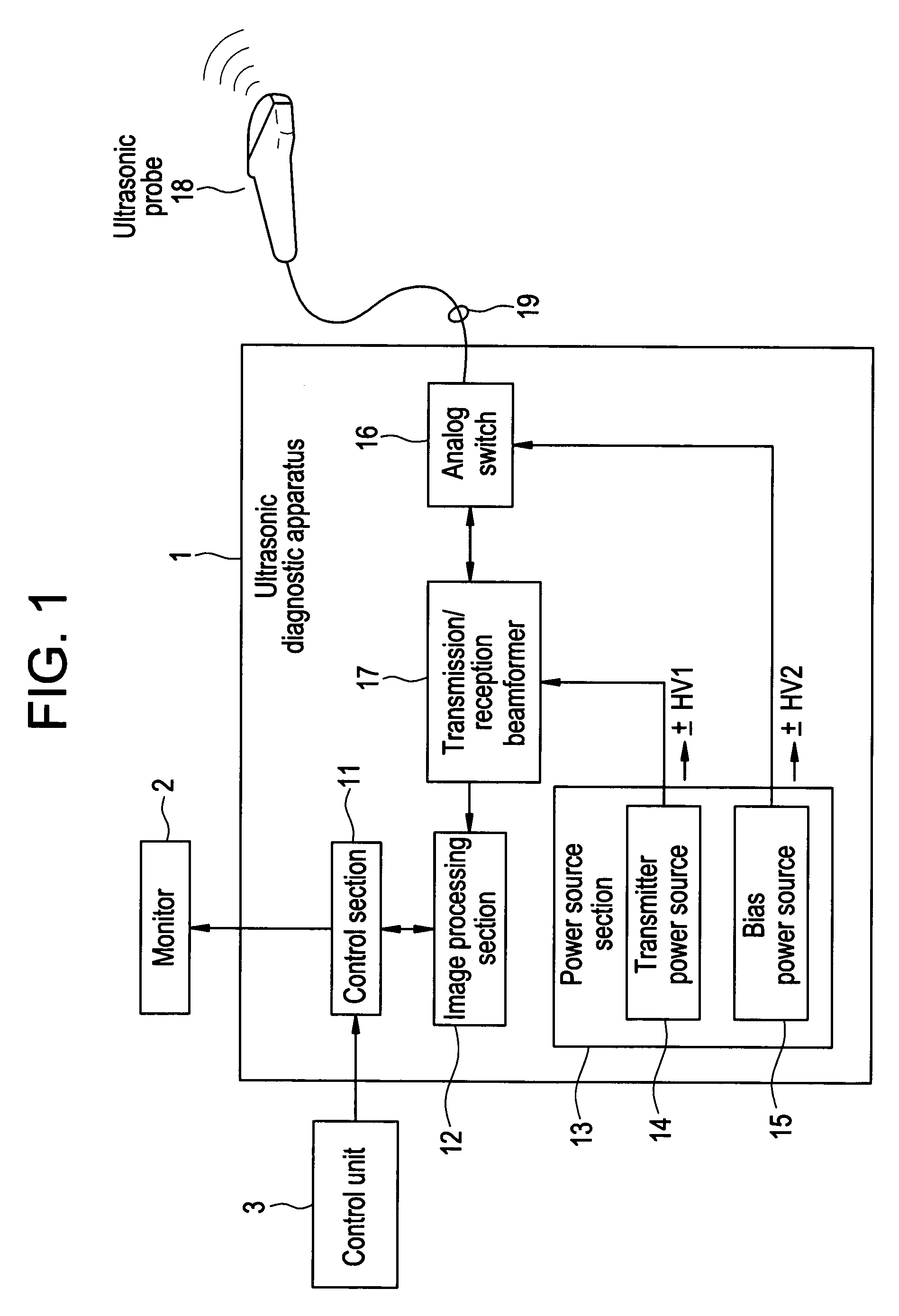
[0033]FIG. 1 is an explanatory diagram for explaining the overall configuration of an ultrasonic diagnostic apparatus in accordance with an embodiment of the present invention. In FIG. 1, an ultrasonic diagnostic apparatus 1 is connected to a monitor 2, a control unit 3 and an ultrasonic probe 18. For the monitor 2, any monitor, such as a CRT or liquid crystal monitor, may be used. The control unit 3 may be a general-purpose input device such as a keyboard or mouse, or may be provided with a dedicated console panel.

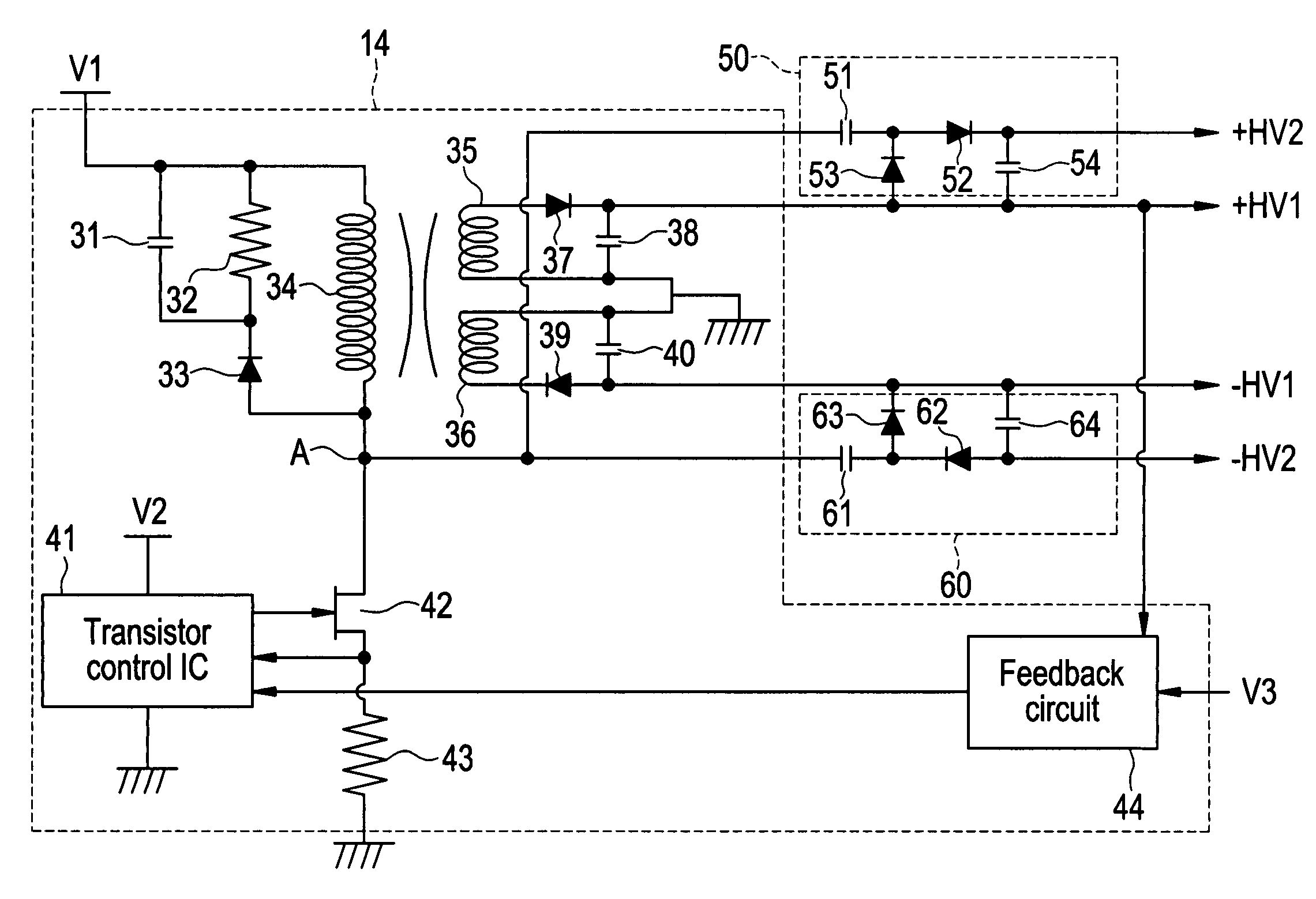
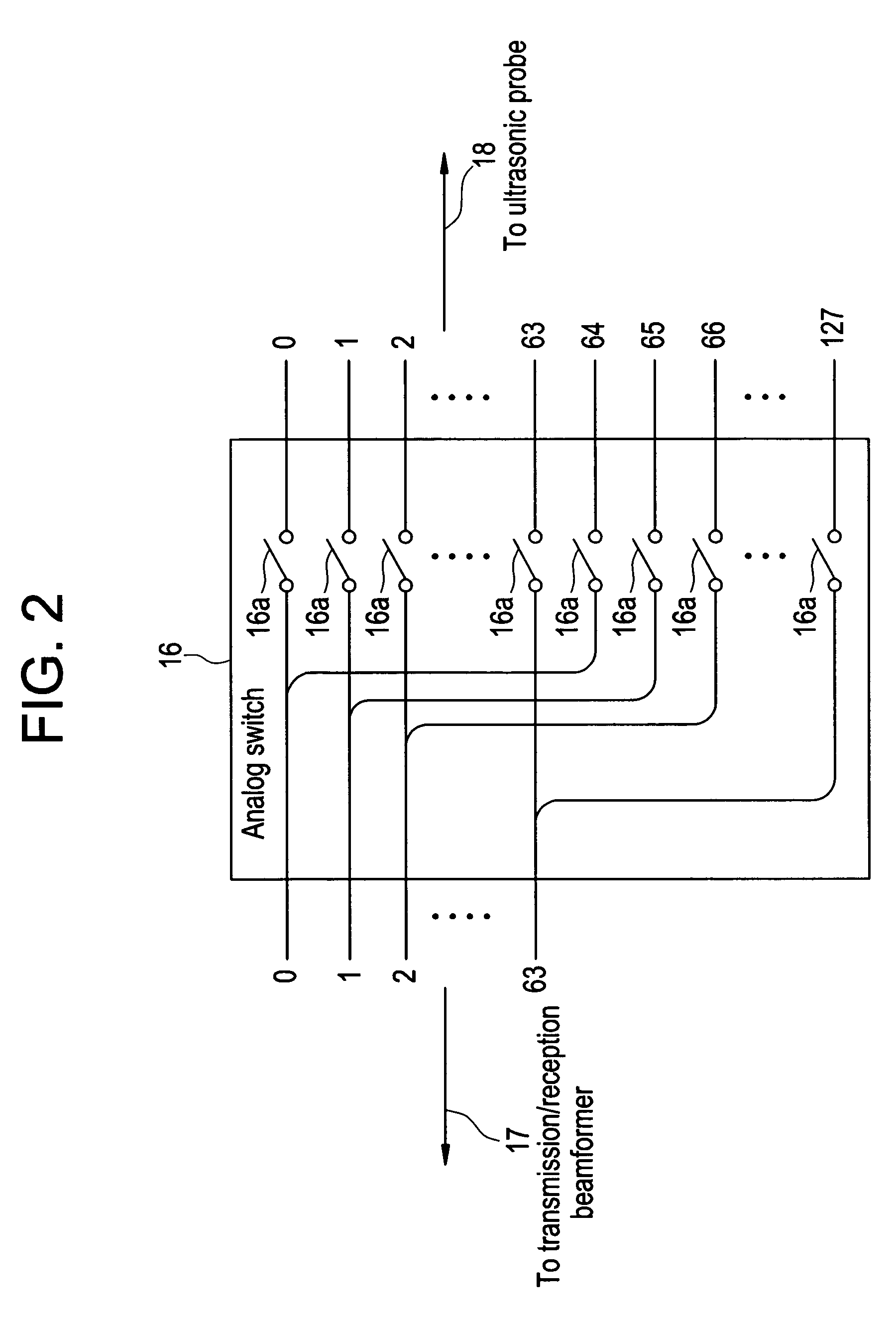
[0034]The ultrasonic diagnostic apparatus 1 also comprises therein a control section 11, an image processing section 12, a power source section 13, an analog switch 16 and a transmission / reception beamformer 17. Moreover, the power source section 13 has therein a transmitter power source 14 and a bias po...


PUM


Abstract

For the purpose of reducing the size and power consumption of a power source in an ultrasonic diagnostic apparatus, charge pump circuits are connected to a transmitter power source. A regulator in the transmitter power source drives the charge pump circuit to generate a positive bias voltage +HV2 higher than a positive voltage +HV1 generated by the transmitter power source. The regulator in the transmitter power source also drives the charge pump circuit to generate a negative bias voltage −HV2 lower than a negative voltage −HV1 generated by the transmitter power source.

Description

CROSS REFERENCE TO RELATED APPLICATIONS[0001]This application claims the benefit of Japanese Application No. 2003-029405 filed Feb. 6, 2003.BACKGROUND OF THE INVENTION[0002]The present invention relates to an ultrasonic diagnostic apparatus for transmitting ultrasonic signals from ultrasonic transducers toward a subject to be examined, and receiving reflected waves of the ultrasonic signals for display, and more particularly to an ultrasonic diagnostic apparatus of small size and low power consumption.[0003]Conventionally, an ultrasonic diagnosis for imaging the interior of a subject by applying ultrasound to a region to be examined in the subject with an abutting ultrasonic probe, and producing an image of echo signals of reflected waves of the applied ultrasound is commonly used. Since ultrasound is harmless to a living body, the ultrasonic diagnostic apparatus is especially useful for medical applications and is used for detection of foreign material in the living body, determina...

Claims


Application Information

Patent Timeline
IPC IPC(8): A61B8/00B06B1/02G01S7/524
CPCB06B1/0215G01S7/52019B06B2201/76A61B8/44A61B8/00
Inventor AMEMIYA, SHINICHI
Owner GE MEDICAL SYST GLOBAL TECH CO LLC
Why Eureka
Try Eureka