Well bore servicing fluids comprising thermally activated viscosification compounds and methods of using the same

a technology of viscosity compound and servicing fluid, which is applied in the direction of fluid removal, wellbore/well accessories, chemistry apparatus and processes, etc., can solve the problems of inability to achieve thermal thinning, etc., to achieve the effect of increasing the viscosity of the servicing fluid

Active Publication Date: 2008-04-01
HALLIBURTON ENERGY SERVICES INC
View PDF34 Cites 47 Cited by
  • Summary
  • Abstract
  • Description
  • Claims
  • Application Information

AI Technical Summary

Problems solved by technology

As such, the fluids undesirably undergo thermal thinning as they pass down the well bore where they are exposed to increasing temperatures.
However, the resulting fluids are very viscous at the earth's surface and thus require relatively high pump pressures to be conveyed downhole.
In addition, they also experience thermal thinning as they pass down the well bore.
Unfortunately, the thermal thinning of fluids as they pass down the well bore typically leads to various problems, depending on the type of fluid involved.
Thus, the drill cuttings may settle out of the drilling fluid and become deposited in undesired locations in the well bore.
Furthermore, those fluids containing particles such as the cement slurry, the gravel packing fluid, and the fracturing fluid may experience settling of the particles as the fluids are pumped down the well bore.
As a result, the particles are not transported to their proper locations in the well bore.
Further, in the absence of such particles, the density of the fluids may drop to a level at which they are incapable of withstanding relatively high fluid pressures downhole, particularly in the case of a high density cement slurry.

Method used


Image

  • Well bore servicing fluids comprising thermally activated viscosification compounds and methods of using the same

Examples


example 1

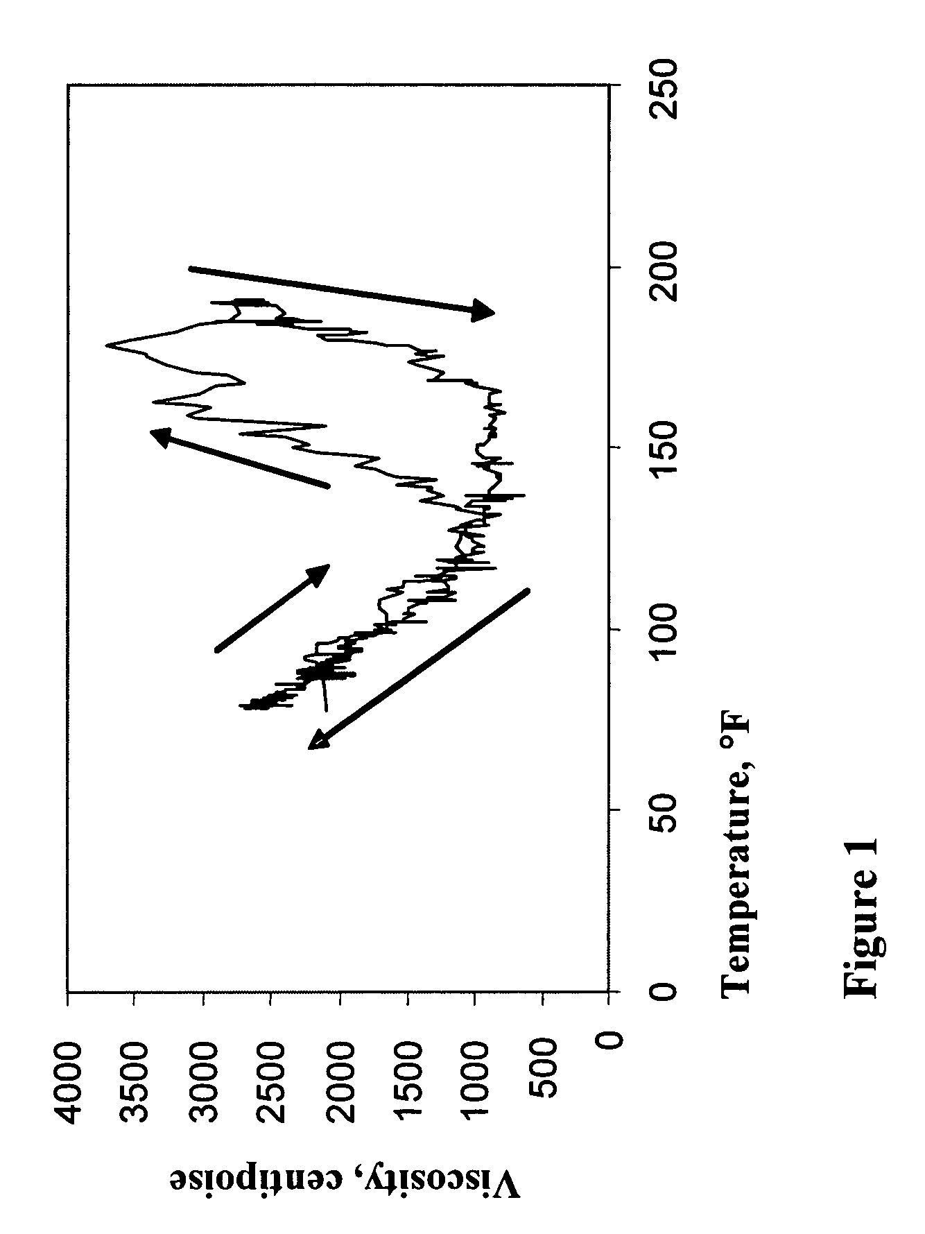
[0023]An aqueous solution containing 2% thermoreversible acrylic polymer by weight of the solution was placed in a 50 mL graduated cylinder. The cylinder containing the polymer solution was then placed in a mineral oil heating bath. A No. 3 spindle was attached to a BROOKFIELD viscometer (model DV-II+) manufactured by Brookfield Engineering Lab Inc. of Middleboro, Mass., and the spindle was immersed in the polymer solution. The mineral oil was heated a few degrees at a time while measuring the viscosity of the polymer solution. After reaching the maximum temperature, the temperature was decreased at a rate of a few degrees per minutes. Table 1 below shows the average viscosity of the polymer solution for each temperature interval. In addition, FIG. 1 depicts the viscosity of the polymer solution as a function of temperature.

[0024]

TABLE 1Temperature Rang, ° F.Average Viscosity, centipoise77-962,260 97-1001,750101-1181,300119-165900166-1801,400181-1602,900161-1301,500131-1081,150107-7...

example 2

[0025]The polymer solution in Example 1 was diluted such that the amount of the thermoreversible acrylic polymer present in the solution was 1% by weight of the solution. Moreover, sodium chloride in an amount of 1% by weight of the polymer solution was added to the solution. The viscosity of the resulting polymer solution was measured as described in Example 1. The results are shown in Table 2 below.

[0026]

TABLE 2Temperature Range,° F.Average Viscosity, Centipoise78-99128100-118210119-17085169-1004399-8438084-77250

The results in Table 2 suggest that the thermoreversible acrylic polymer and an ionic compound can be used in combination to form a solution that viscosifies reversibly with temperature in certain temperature ranges. Thus, the polymer can serve as a thermally activated viscosification compound in a well bore servicing fluid. The results also show that the viscosification temperature range may or may not be identical during heating and cooling cycles or vice versa.


PUM

PropertyMeasurementUnit
water-solubleaaaaaaaaaa
hydrophilicaaaaaaaaaa
hydrophobicaaaaaaaaaa

Abstract

Well bore servicing fluids are provided that include a thermally activated viscosification compound. Further, methods of servicing a well bore are provided that include displacing such a servicing fluid into the well bore, wherein a viscosity of the servicing fluid increases as it passes down the well bore due to its temperature increasing. Thus, the viscosity of the servicing fluid is effective to suspend solids therein when the servicing fluid is in the well bore. The servicing fluid may be, for example, a cement slurry, a drilling fluid, a gravel packing fluid, a fracturing fluid, a completion fluid, or a work-over fluid. In an embodiment, the thermally activated viscosification compound includes at least one water-soluble hydrophobically modified polymer comprising a hydrophobic substituent having from about 1 to about 22 carbon atoms.

Description

FIELD OF THE INVENTION[0001]This invention generally relates to well bore servicing fluids and methods of servicing a well bore. More specifically, the invention relates to methods of servicing a well bore using a servicing fluid comprising a thermally activated viscosification compound for promoting the suspension of particles in the servicing fluid.BACKGROUND OF THE INVENTION[0002]Natural resources such as gas, oil, and water residing in a subterranean formation can be recovered using well-known techniques. The steps taken to prepare for the recovery of such resources usually require the use of various fluids. For example, drilling fluids or muds are typically circulated through well bores as they are drilled into the formation. During the drilling process, the drill bit generates drill cuttings that consist of small pieces of shale and rock. The drilling fluid carries the drill cuttings in a return flow stream back to the well drilling platform. After terminating the circulation ...

Claims


Application Information

Patent Timeline
Patent Type & Authority Patents(United States)
IPC IPC(8): C09K8/88E21B21/00E21B33/00C09K8/035C09K8/68C09K8/70
CPCC09K8/035C09K8/68C09K8/685C09K8/706
Inventor REDDY, B. RAGHAVAZAMORA, FRANKKOCH, RONNEY R.SANDY, JOE M.ROBB, IAN D.
Owner HALLIBURTON ENERGY SERVICES INC
Why Eureka
Try Eureka