Method and implementation for adaptive symbol decision mapping

Inactive Publication Date: 2008-04-01
CISCO TECH INC
View PDF8 Cites 17 Cited by
  • Summary
  • Abstract
  • Description
  • Claims
  • Application Information

AI Technical Summary

Benefits of technology

[0011]The difficulties and drawbacks associated with previous systems are overcome by the method and implementation of the present invention for reducing signal distortion. A symbol detector is provided for establishing at least one decision boundary and assigning symbols extracted from a received signal to constellations of symbols separated by the at to least one decision boundary. A qual

Problems solved by technology

In any case, the process of correctly deciding how a given symbol maps into a digital number directly affects the error rate and hence the overall performance of the communication system—the better the symbol map decision, the lower the error rate.
Thus, the decision circuit effectively establishes a decision boundary 14 in the complex plane to distinguish between symbols representing a digital “1” and a “0.” Factors such as noise and distortion can create difficulties in establishing a decision boundary, thereby increasing the signal's bit-error rate (BER).
But considering the effects of noise and filtering, the slicer is effectively “off-center,” and some symbols will be incorrectly assigned to the wrong side of the decision boundary, resulting in an excessive increase in the bit-error rate.
In higher order schemes, such as QPSK (Quadrature Phase Shift Keying) and QAM (Quadrature Amplitude Modulation), the problems with noise and distortion are increased.
Since the symbol map is essentially fixed by the analog signal amplitude, the decision process can fall prey to mapping distortions in the mod

Method used


Image

  • Method and implementation for adaptive symbol decision mapping
  • Method and implementation for adaptive symbol decision mapping
  • Method and implementation for adaptive symbol decision mapping

Examples


Embodiment Construction

[0019]The present invention comprises a symbol decision circuit for backing out any distortions of a received symbol constellation, and thereby produce an undistorted map. The invention accomplishes adaptive symbol decision mapping by modifying symbol decision boundaries in a complex plane so as to reduce the effects of symbol constellation distortion on the performance of the digital communication system.

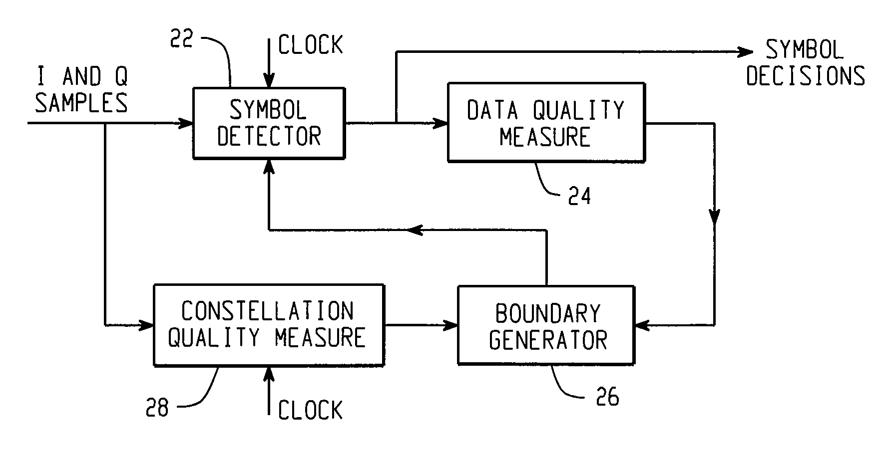
[0020]The symbol decision circuit 20 of the present invention is shown in FIG. 6. The in-phase and quadrature (I and Q) samples from a receiver's demodulator are presented to a symbol detector 22. Within the symbol detector 22, symbol decisions are made at the clock rate based upon where the complex samples fall relative to presumed initial decision boundaries. The output of the symbol detector 22 is processed by a data quality measure 24 that determines the bit-error rate of the symbols. The output of the data quality measure circuit 24 is received by a boundary generator 26 that ...


PUM


Abstract

A method and implementation are disclosed for reducing signal distortion. A symbol detector is provided for establishing at least one decision boundary and assigning symbols extracted from a received signal to constellations of symbols separated by the at least one decision boundary. A quality measure implementation is provided for determining an error rate of the output of the symbol detector with respect to the at least one decision boundary. A boundary generator is provided for receiving the error rate and generating parameters that are fed back to the symbol detector to vary the decision boundary positions and shapes, so as to reduce the error rate of the symbol detector.

Description

BACKGROUND[0001]The present invention is directed to the field of digital telecommunications, particularly systems that employ complex channel modulation techniques. In signal transmission, digital data is typically modulated onto an analog carrier, such as with M-PSK (M-ary Phase Shift Keying) or QAM (Quadrature Amplitude Modulation). In such schemes, it is typical to modulate data into two non-interfering orthogonal signal paths, I and Q (In-phase and Quadrature).[0002]By way of example, a Binary Phase Shift Keying (BPSK) scheme is depicted in FIGS. 1A-1D. During reception of the signal, as shown in FIG. 1A, the analog subcarrier signal is demodulated at the receiver into digital data by taking samples 10 at predetermined intervals. If a positive voltage is detected, a digital value of “1” is indicated. A negative voltage indicates a digital value of “0.” The samples 10 are taken at predetermined intervals at which time a sample decision is made, derived from a clock reference, wh...

Claims


Application Information

Patent Timeline
IPC IPC(8): H04L27/08H04B1/10
CPCH04L25/06H04L27/3863
Inventor LEWIS, MICHAEL E.THEOBOLD, DAVID M.
Owner CISCO TECH INC
Why Eureka
Try Eureka