Method and apparatus of providing power to ignite and sustain a plasma in a reactive gas generator

a technology of reactive gas and plasma, which is applied in the direction of plasma technique, coating, electric lighting sources, etc., can solve the problems of general cost and inability to meet the needs of power generation,

Active Publication Date: 2008-04-08
MKS INSTR INC
View PDF34 Cites 44 Cited by
  • Summary
  • Abstract
  • Description
  • Claims
  • Application Information

AI Technical Summary

Benefits of technology

[0006]The invention features methods and power supplies that provide power to ignite and sustain a plasma in a reactive gas generator. Advantages of particular embodiments include prevention of damage to power supply semiconductor devices at reduced cost and increased reliability and performance.
[0008]Particular embodiments can further include providing a first AC voltage from the switching power source across the series resonant circuit, the first AC voltage having a frequency at a substantially resonant frequency of the series resonant circuit; in response to the first AC voltage, providing the substantially resonant AC voltage from the resonant capacitor across the transformer primary, thereby inducing the substantially resonant current within the transformer primary to generate the plasma secondary; and modulating the frequency of the first AC voltage from the switching power source to a frequency greater than the substantially resonant frequency of the series resonant circuit to further limit the current flowing to the switching power supply subsequent to generation of the plasma secondary.

Problems solved by technology

However, such techniques are generally costly and are not reliable.

Method used


Image

  • Method and apparatus of providing power to ignite and sustain a plasma in a reactive gas generator
  • Method and apparatus of providing power to ignite and sustain a plasma in a reactive gas generator
  • Method and apparatus of providing power to ignite and sustain a plasma in a reactive gas generator

Examples


Embodiment Construction

[0022]The invention features methods and power supplies that provide power to ignite and sustain a plasma in a reactive gas generator. Advantages of particular embodiments include prevention of damage to power supply semiconductor devices at reduced cost and increased reliability and performance.

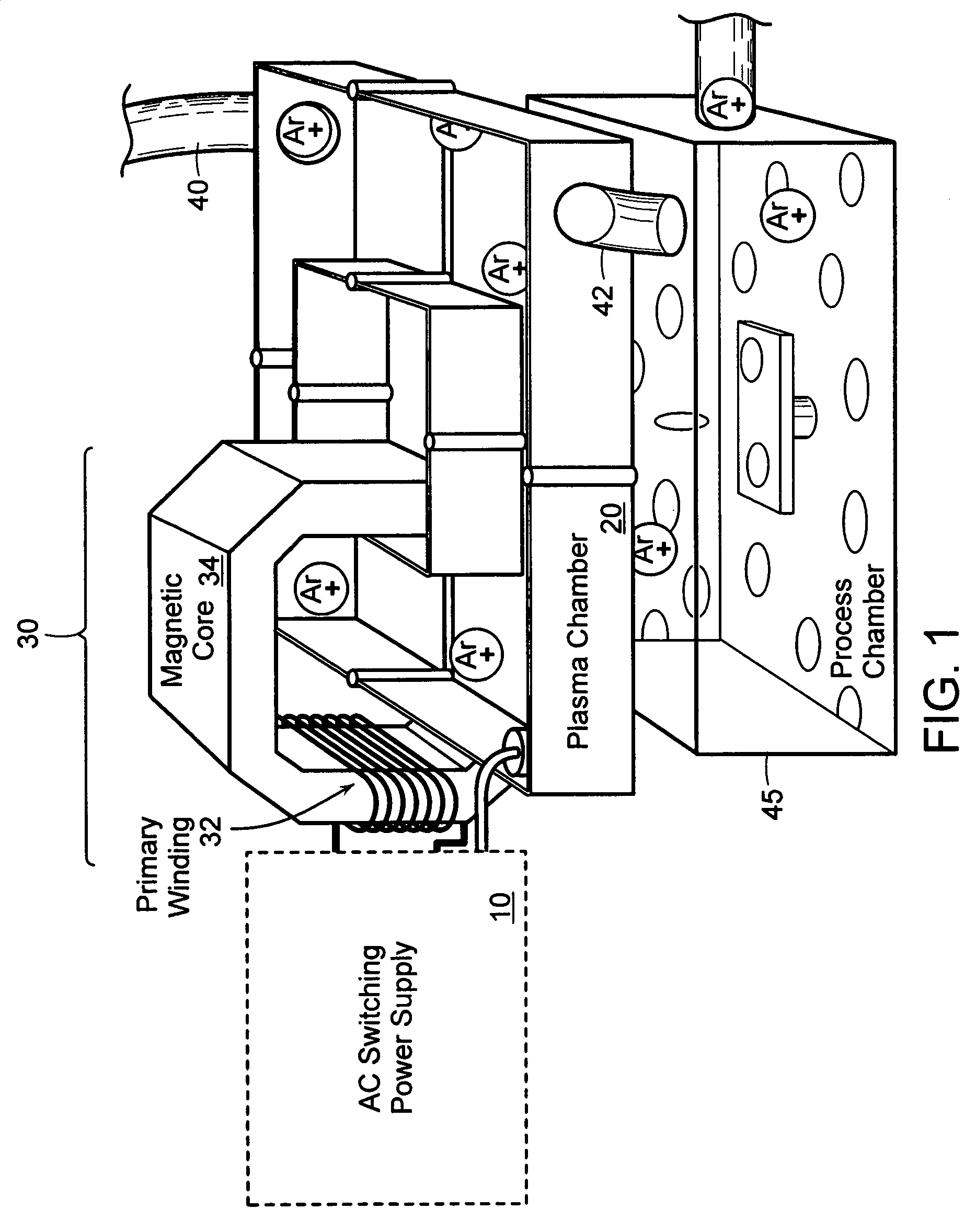
[0023]FIG. 1 is a diagram illustrating a reactive gas generator to which embodiments of the invention may be applied. As illustrated, the reactive gas generator 1 includes a power supply 10 and a plasma chamber 20. The plasma chamber 20 includes an inlet 40 for receiving a gas (e.g., Argon) for transformation into a plasma (e.g., Ar+). Once generated, the plasma may be used directly, or can be used to excite one or more other source gases into corresponding reactive gases that exit the generator at outlet 42 and into, for example, a process chamber 45.

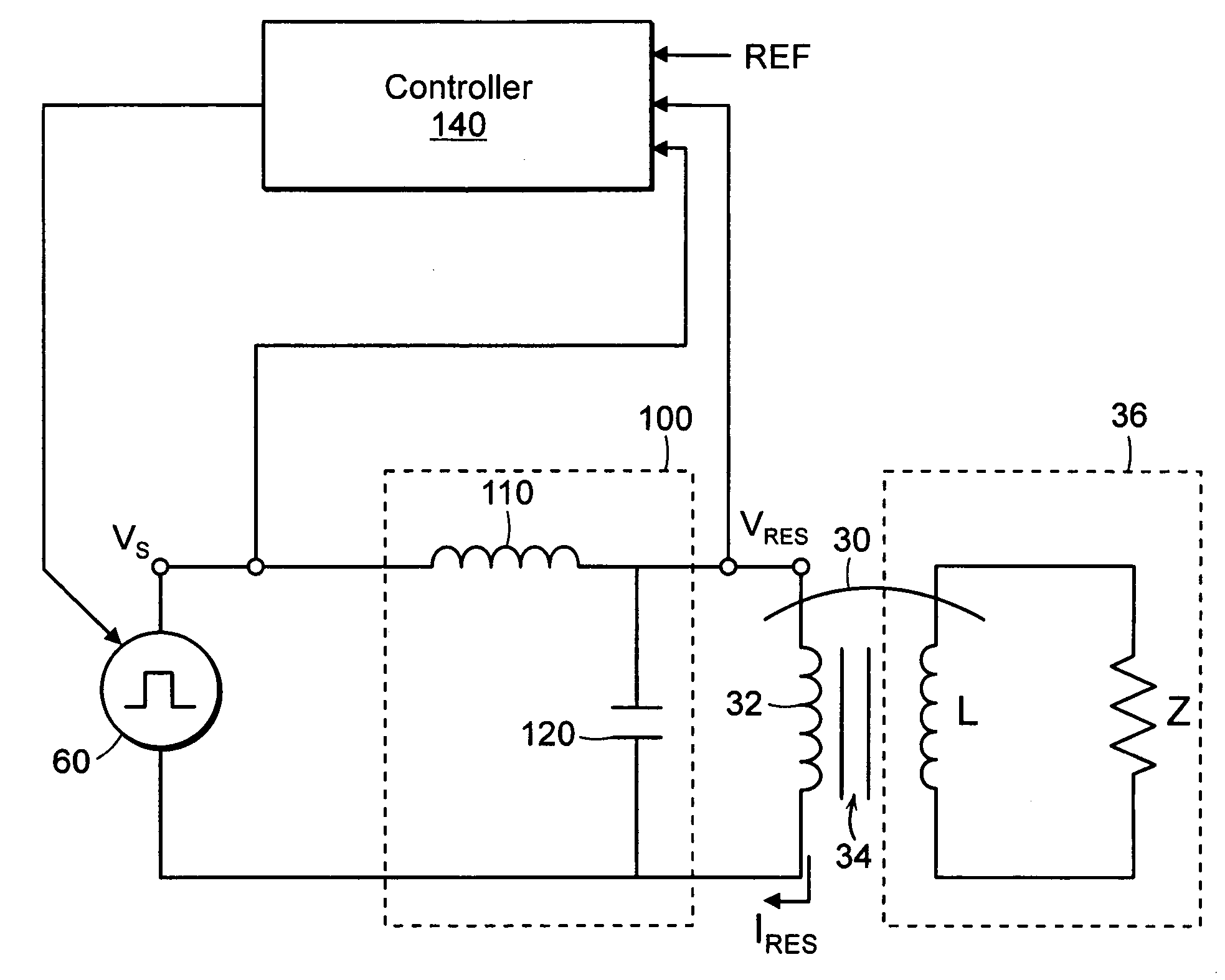
[0024]In order to ignite the plasma, the power supply 10 includes a transformer 30. The transformer primary includes a primary winding 32 wrap...


PUM

PropertyMeasurementUnit
poweraaaaaaaaaa
voltageaaaaaaaaaa
frequencyaaaaaaaaaa

Abstract

According to a first aspect, a power supply and a method of providing power for igniting a plasma in a reactive gas generator is provided that includes (i) coupling a series resonant circuit that comprises a resonant inductor and a resonant capacitor between a switching power source and a transformer, the transformer having a transformer primary and a plasma secondary; (ii) providing a substantially resonant AC voltage from the resonant capacitor across the transformer primary, thereby inducing a substantially resonant current within the transformer primary to generate the plasma secondary; and (iii) upon generation of the plasma secondary, the resonant inductor limiting current flowing to the switching power supply. According to another aspect, bipolar high voltage ignition electrodes can be used in conjunction with inductive energy coupling to aid in plasma ignition.

Description

FIELD OF THE INVENTION[0001]The invention relates generally to the field of generating reactive gas containing ions, free radicals, atoms and molecules and to apparatus for and methods of providing power for igniting a plasma in a reactive gas generator.BACKGROUND OF THE INVENTION[0002]Plasma discharges can be used to excite gases to produce reactive gas containing ions, free radicals, atoms and molecules. Reactive gases are used for numerous industrial and scientific applications including processing solid materials such as semiconductor wafers, powders, and other gases.[0003]One example of a reactive gas is atomic fluorine, which can be used to clean chemical vapor deposition (CVD) chambers for deposition of thin films onto substrate surfaces. CVD chambers need to be routinely cleaned to remove the deposits that build up on the surfaces of chamber parts other than the substrate surfaces. Wet cleaning of a chamber is labor intensive and hazardous to workers, while cleaning the cham...

Claims


Application Information

Patent Timeline
Patent Type & Authority Patents(United States)
IPC IPC(8): C23C16/00
CPCH01J37/321H05H1/46H01J37/32174H01J37/32137H01J37/32
Inventor MILLNER, ALANALEXANDER, THOMASBYSTRYAK, ILYATRAN, KENJOSHI, MADHUWANTI
Owner MKS INSTR INC
Why Eureka
Try Eureka