Electrical connector

a technology of electrical connectors and plugs, applied in the field of plug connectors, can solve the problems of failure of connection, unavoidable flat geometry of plug connectors, and inability to realize flat geometry less than 1.4 mm of plug connectors as problems to be solved, and achieve the effect of preventing any defective connection

Inactive Publication Date: 2008-04-08
DDK LTD
View PDF19 Cites 13 Cited by
  • Summary
  • Abstract
  • Description
  • Claims
  • Application Information

AI Technical Summary

Benefits of technology

[0014]It is an object of the invention to provide an improved electrical connector which eliminate all the disadvantages of the prior art, and which achieves the flat geometry of its plug connector 60 and hence of its receptacle connector 80 to the desired extent and can preclude any defective connection between a ground bar 66 and coaxial cables 14.

Problems solved by technology

With the construction of the plug connector described above, however, the thicknesses of the plug contacts and the thickness of the block required for holding the plug contacts have minimum limitations which make it impossible to realize a flat geometry less than 1.4 mm of the plug connector as a problem to be solved.
Therefore, the flat geometry of the plug connector is unavoidable in order to achieve the flat geometry of the receptacle connector.
With the construction of the plug connector, moreover, in the case that coaxial cables having a fine diameter are used with a narrow pitch, when the braids of the coaxial cables are connected to the ground bar by soldering, the insulators of the coaxial cables tend to melt by the heat of the soldering to cause the continuity of the braids and the center conductors, resulting into failed connection.
With the construction of the plug connector described above, as the coaxial cables are connected to a rigid body not having a flexibility, the connection portions of the coaxial cables tend to be partly broken depending on the used condition such as being bent, resulting into defective connection.

Method used


Image

  • Electrical connector
  • Electrical connector
  • Electrical connector

Examples


Embodiment Construction

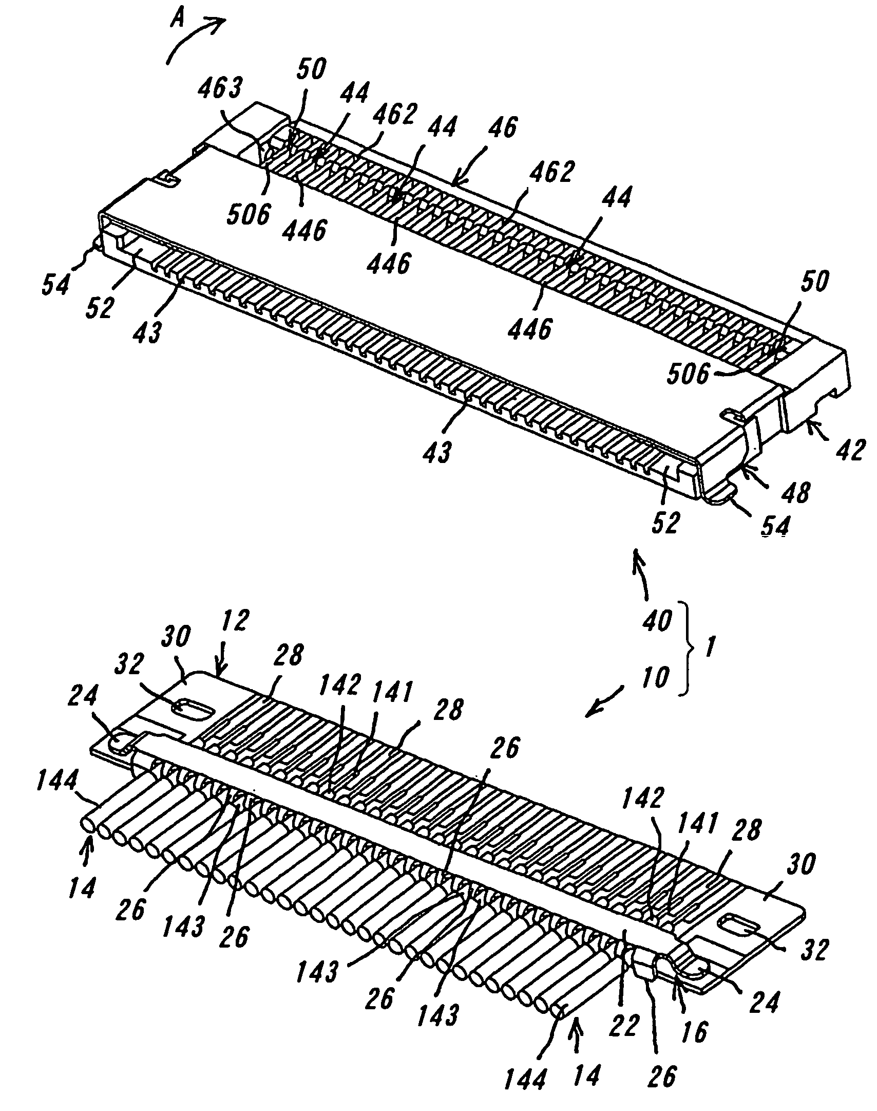
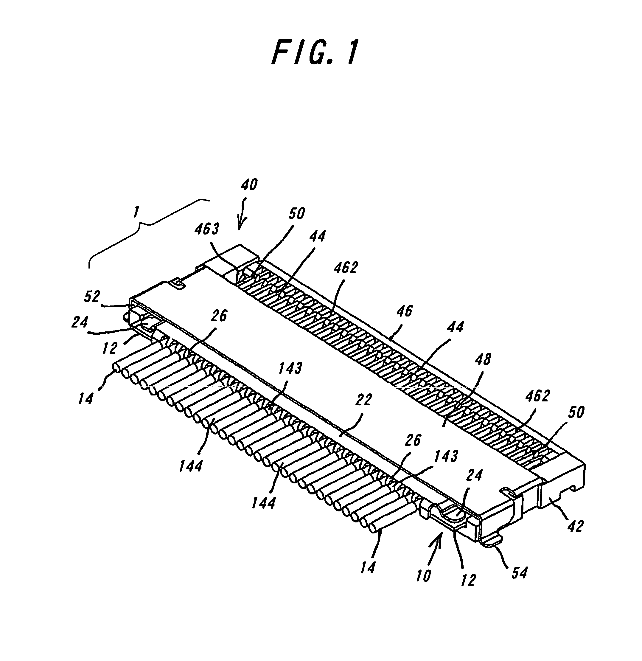
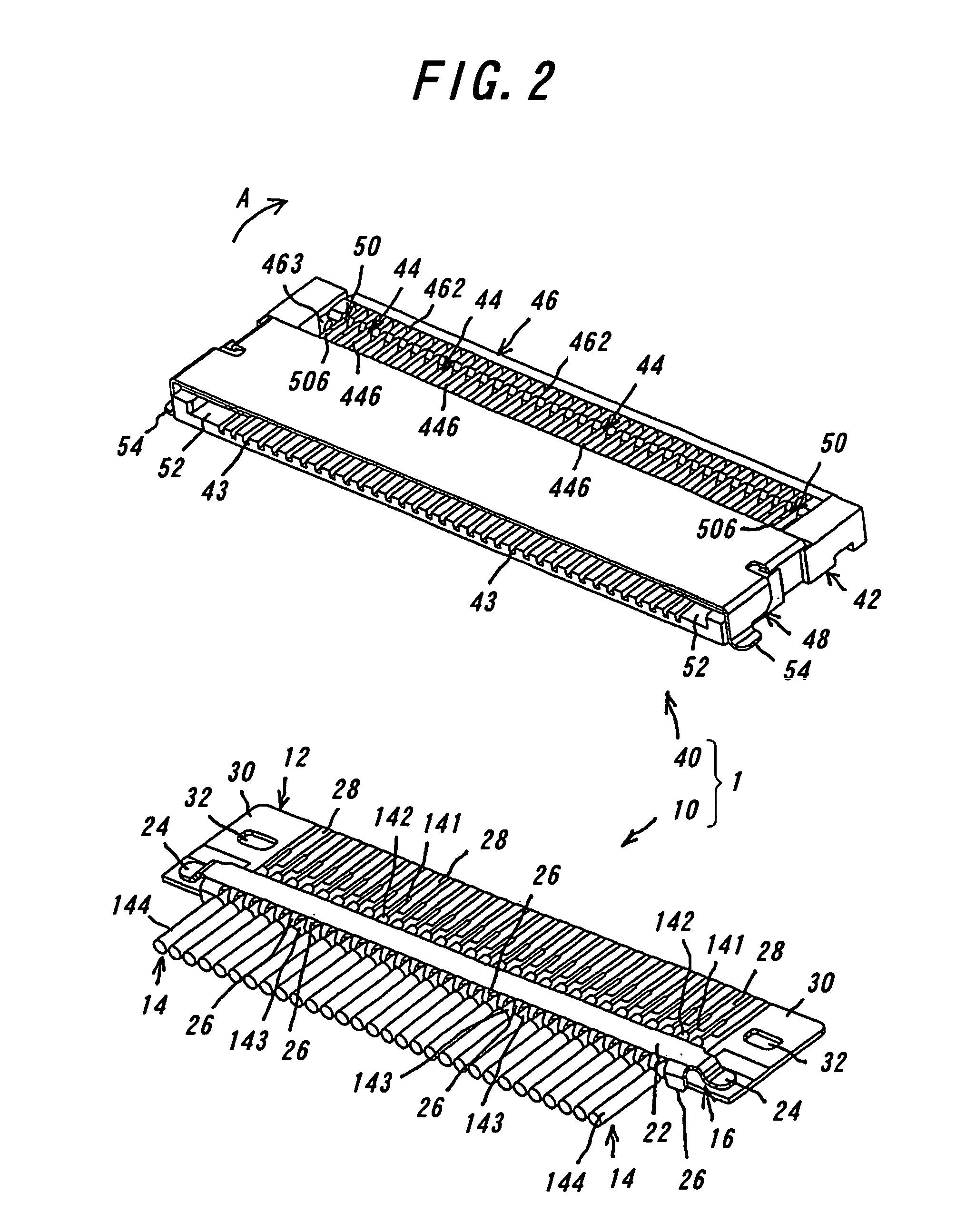
[0115]An electrical connector according to one embodiment of the invention will be explained with reference to the drawings. The electrical connector 1 comprises a plug connector 10 and a receptacle connector 40 which are to be detachably fitted with each other. FIG. 1 illustrates in a perspective view the plug connector and the receptacle connector according to the invention fitted with each other. FIG. 2 shows in a perspective view the plug connector and the receptacle connector according to the invention prior to the fitting with each other. FIG. 3 is a perspective view illustrating the plug connector in FIG. 2 being turned upside down. FIG. 4A is a perspective view illustrating the plug connector and contacts and locking members of the receptacle connector according to the invention, and FIG. 4B is a perspective view illustrating the contacts and locking members of the receptacle connector, which are in contact with the plug connector according to the invention. FIG. 5 illustrat...


PUM


Abstract

An electrical connector includes a plug connector and a receptacle connector detachably fitted with each other. The plug connector comprises a plurality of coaxial cables, a flexible printed circuit board and a ground bar. Each of the coaxial cable has a center conductor, an insulator covering the center conductor, a braid as an external conductor covering the insulator, and a sheath covering the braid. The flexible printed circuit board has lands each connected to the center conductor of the coaxial cable and land portions to which the ground bar is connected. The grand bar has a main portion adapted to contact the braids of the coaxial cables, and fixed portions each positioned contiguously with the main portion and connected to the land portion. The electrical connector achieves the low height geometry of the plug connector and hence that of the receptacle connector and precludes any failed connection between the ground bar and the coaxial cables.

Description

CROSS-REFERENCE TO RELATED APPLICATIONS[0001]This application is a national phase of International Application No. PCT / JP04 / 018688, filed Dec. 8, 2004, which claims priority from Japanese Patent Application No. 2004-1,524, filed Jan. 7, 2004, each of which are incorporated by reference in their entireties herein, and from which priority is claimed.TECHNICAL FIELD[0002]This invention relates to a plug connector for use with appliances such as a mobile phone or cellular telephone, notebook personal computer, digital camera and the like, and more particularly to a construction for achieving the flat geometry of a plug connector.[0003]There is no particularly relevant patent literature disclosed within scope of our research. In order to reduce the noise in appliances, coaxial cables 14 have frequently been used because of their shielding effects. For example, as shown in FIGS. 8 and 9, for the purpose of connecting the coaxial cables 14 to a hard substrate, a plug connector 60 and a rec...

Claims


Application Information

Patent Timeline
Patent Type & Authority Patents(United States)
IPC IPC(8): H01R9/05H05K1/11H05K3/34
CPCH01R9/0512H01R9/0515H01R12/61H01R12/598H05K1/117H05K3/3405H01R9/05H01R24/00
Inventor YAMADA, AKIOHIROMICHI, KATO
Owner DDK LTD
Why Eureka
Try Eureka