
Drive system for regulating devices in motor vehicles

a technology of regulating device and drive system, which is applied in the direction of wing accessories, gearing, hoisting equipment, etc., can solve the problems of mechanical stability of the planet wheel transmission, premature wear and breakdown of the drive unit, etc., and achieve the effect of easy exchang

Inactive Publication Date: 2008-04-08
BROSE FAHRZEUGTEILE GMBH & CO KG
View PDF13 Cites 7 Cited by
  • Summary
  • Abstract
  • Description
  • Claims
  • Application Information

AI Technical Summary

Benefits of technology

The invention is a solution for producing a drive system for regulating devices in motor vehicles with minimal structural volume. The solution is based on the knowledge that accurate bearing and alignment of component parts is important for the mechanical stability of the drive system. By fitting the fixed drive axle, journal of the output internal geared wheel and drive hub cylinder of the drive hub onto each other, the entire length of the fixed drive axle is used, resulting in a more efficient use of space and reduced structural depth. The length of the drive hub cylinder matches the height of the rollers, which helps to align and secure the armature disc and the output internal geared wheel in a precise manner. The base disc centres both the housing covers and supports the hollow wheel gearing, which also acts as a centring element for the precision alignment and bearing of the component parts of the drive system. The base disc can be connected to a plastics disc to support the permanent magnets, and the permanent magnets can be easily positioned and secured without the need for additional fixing elements. The invention reduces the structural depth of the drive system without compromising its mechanical stability.

Problems solved by technology

As opposed to the drive units normally used comprising rod armature motors with worm gearing as reduction gearing which through their type of construction are not equally suited to right and left hand vehicle doors where the structural height in the door region is an interference and whose installation position is not flexible particularly through rotation of the drive unit, wherein the centre of gravity of the motor lies outside of the screw connection of the drive unit and whose system mass is very high, the drive unit according to the International Patent Application No.
Thus the small air gap between the armature disc and the permanent magnet of the stator of the disc armature motor in the case of a stable mounted armature disc which is not permanently precisely aligned would lead to contact between the armature disc and permanent magnets and thus to premature wear and breakdown of the drive unit.
Furthermore the mechanical stability of the planet wheel transmission would be endangered if the centring of the mechanical component parts is not permanently guaranteed and also under severe strain no deformations of the gearing parts occur.

Method used


Image

  • Drive system for regulating devices in motor vehicles
  • Drive system for regulating devices in motor vehicles
  • Drive system for regulating devices in motor vehicles

Examples


Embodiment Construction

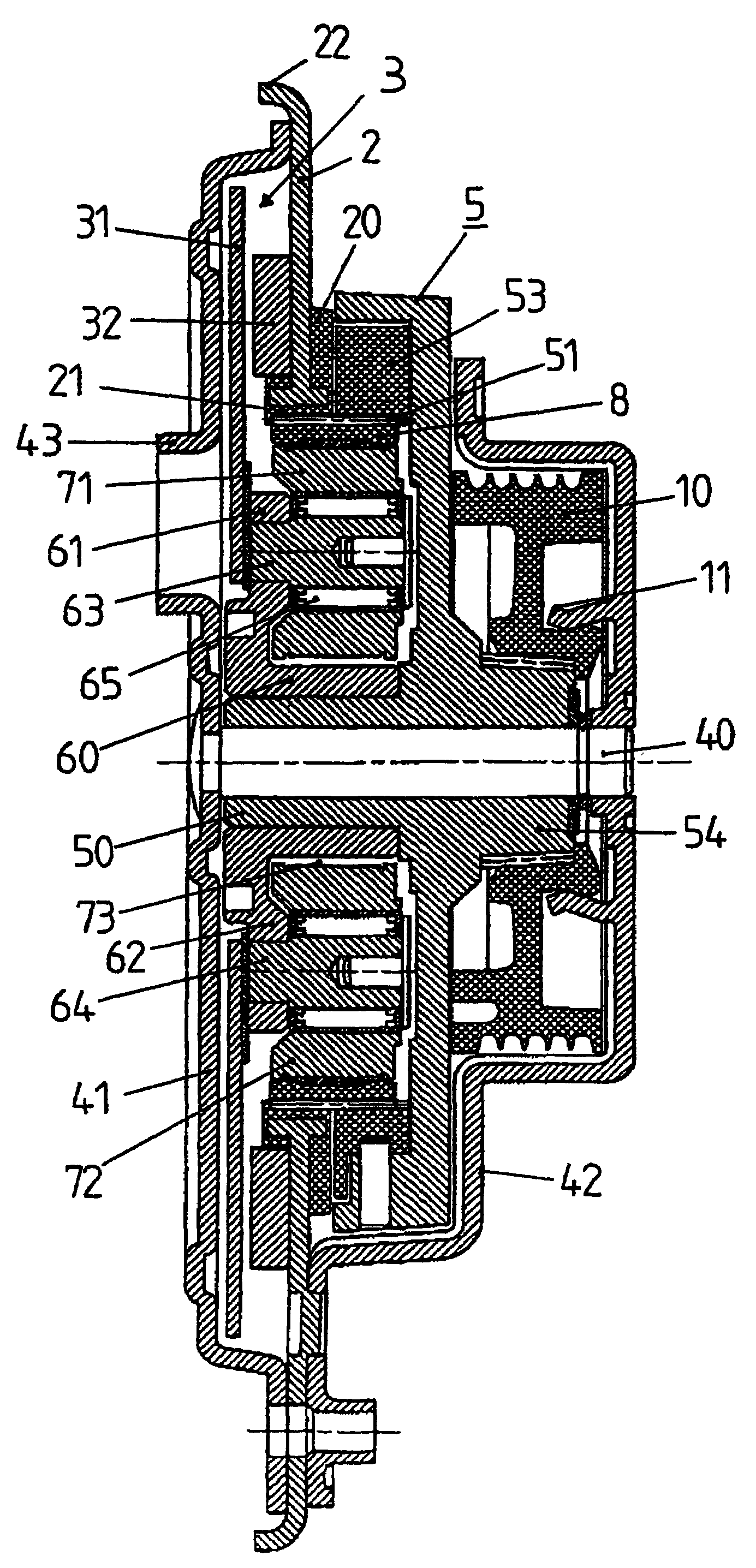
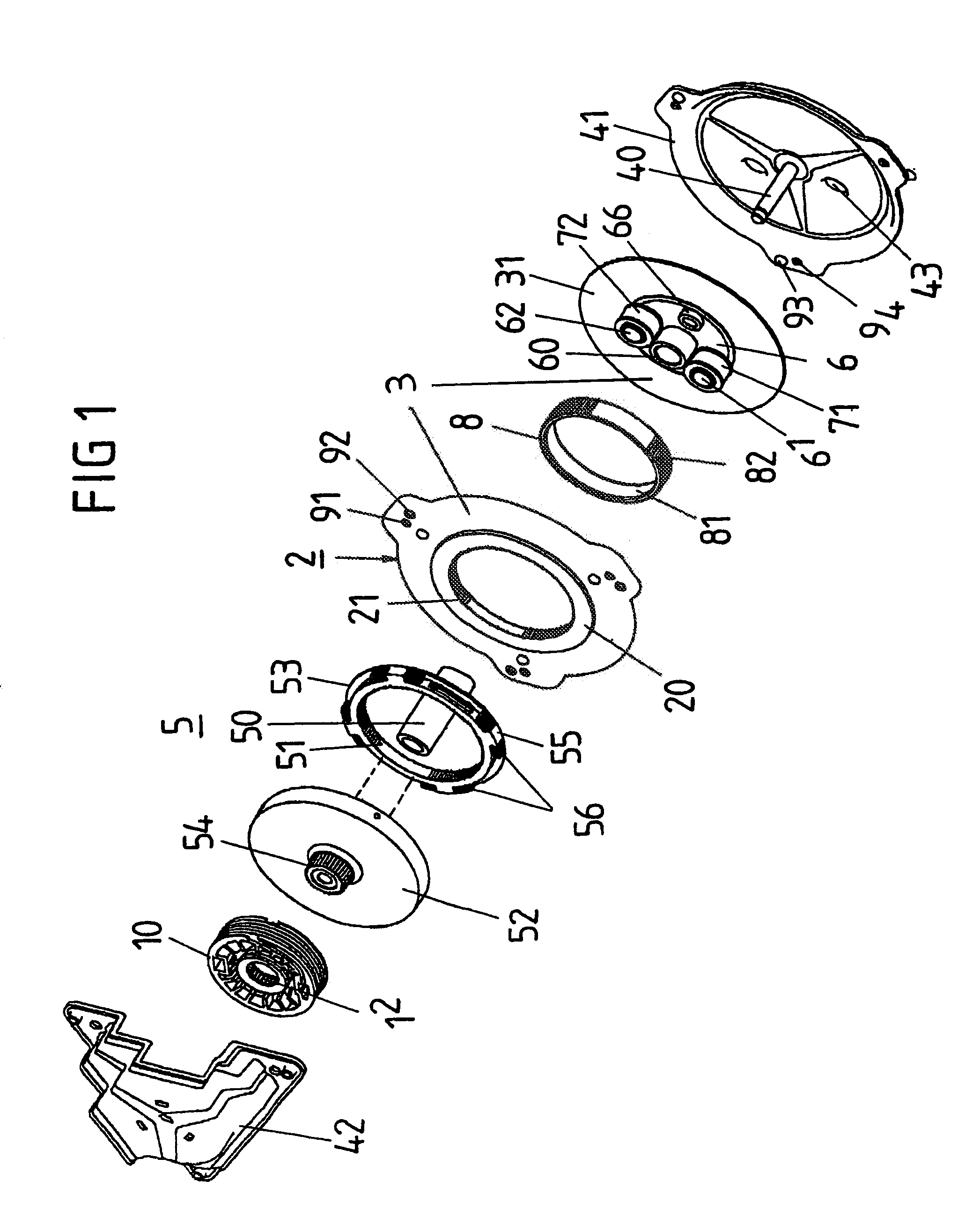
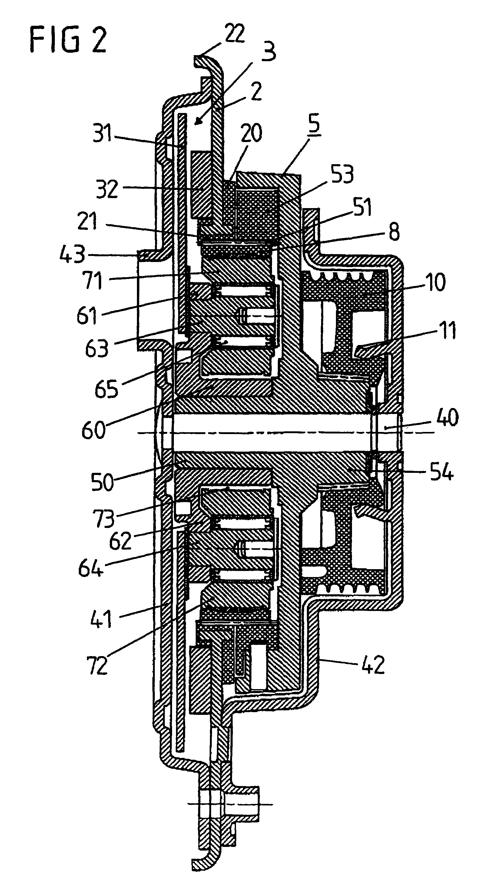
[0036]FIG. 1 shows an exploded view of a drive system illustrated in longitudinal sectional view in FIG. 2 for a cable window lifter of a motor vehicle. The drive system comprises a disc armature motor 3, a planet wheel transmission 5, 6, 21, 71, 72 and a cable drum 10 which are mounted in a housing which comprises two housing covers 41, 42 and is centred on a base disc 2.

[0037]The electronically commutated disc armature motor 3 in this embodiment comprises an armature disc 31 and several permanent magnets 32 arranged spaced out round the circumference of the base disc 2 (FIG. 2). The armature disc 31 is connected to a drive hub 6 which is preferably formed as a stamped steel part and has a passage formed as a drive hub cylinder 60 as well as two passages 61, 62 for two roller bearings 63, 64 on which two rollers 71, 72 of the planet wheel transmission are mounted and supported through rolling bearings 65 opposite the rollers 71, 72. Furthermore several cropped angles 66 are provide...


PUM


Abstract

A drive system for regulating devices in motor vehicles comprising a housing containing a drive element of the regulating device, a disk armature motor provided with an armature disk, and a planet wheel transmission. The planet wheel transmission comprises an internal geared wheel fixed to the housing and provided with an internal gear, an output internal geared wheel connected to the drive element of the regulating device and provided with an internal gear, and a radially flexible ring, the external gear thereof partially meshing with the inner gears of the internal geared wheel fixed to the housing and of the output internal geared wheel, and the inner envelope surface thereof rolling on rollers arranged on a drive hub connected to the armature disk. A journal pertaining to the output internal geared wheel is centred between the fixed drive axle and a cylinder of the drive hub.

Description

CROSS-REFERENCE TO A RELATED APPLICATION[0001]This application is a National Phase Patent Application of International Application Number PCT / DE2004 / 001889, filed on Aug. 21, 2004, which claims priority of German Utility Model Number 203 13 273.4, filed on Aug. 21, 2003.BACKGROUND[0002]The invention relates to a drive system for regulating devices in motor vehicles. From an International Patent Application No. WO 01 / 89063 A1 a drive unit is known for regulating devices in motor vehicles having the features of the preamble of claim 1. Since with this known drive unit at least one component part of the disc armature motor such as for example the drive shaft, the magnetic short circuit or the housing shell on the motor side also undertakes an additional mechanical function of the planet wheel transmission and / or a mechanical component part such as the housing shell on the gearing side undertakes a function of the disc armature motor the drive unit is as a result of the multiple use of ...

Claims


Application Information

Patent Timeline
Patent Type & Authority Patents(United States)
IPC IPC(8): F16H48/06E05F11/48E05F15/16E05F15/60H02K7/116
CPCE05F11/483E05F15/697H02K7/116E05Y2201/72E05Y2900/55E05Y2201/49E05Y2800/268E05Y2201/434
Inventor SESSELMANN, HELMUT
Owner BROSE FAHRZEUGTEILE GMBH & CO KG
Learn More