
Microarray detector and methods

a microarray and detector technology, applied in the field of optical detection, can solve the problems of inability to achieve electronic detection, and inability to achieve fast data acquisition

Inactive Publication Date: 2008-04-08
AUTOGENOMICS
View PDF2 Cites 58 Cited by
  • Summary
  • Abstract
  • Description
  • Claims
  • Application Information

AI Technical Summary

Benefits of technology

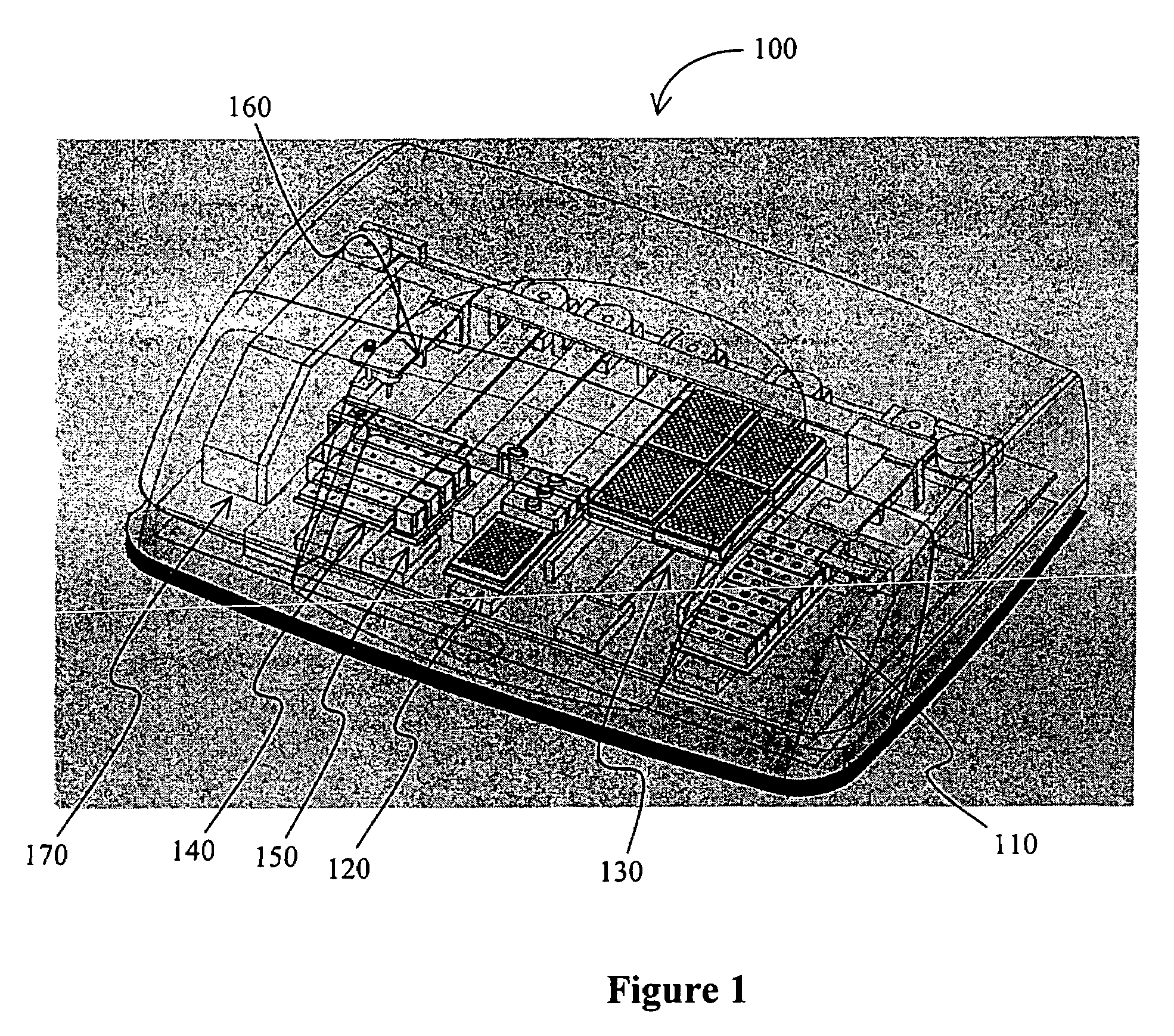
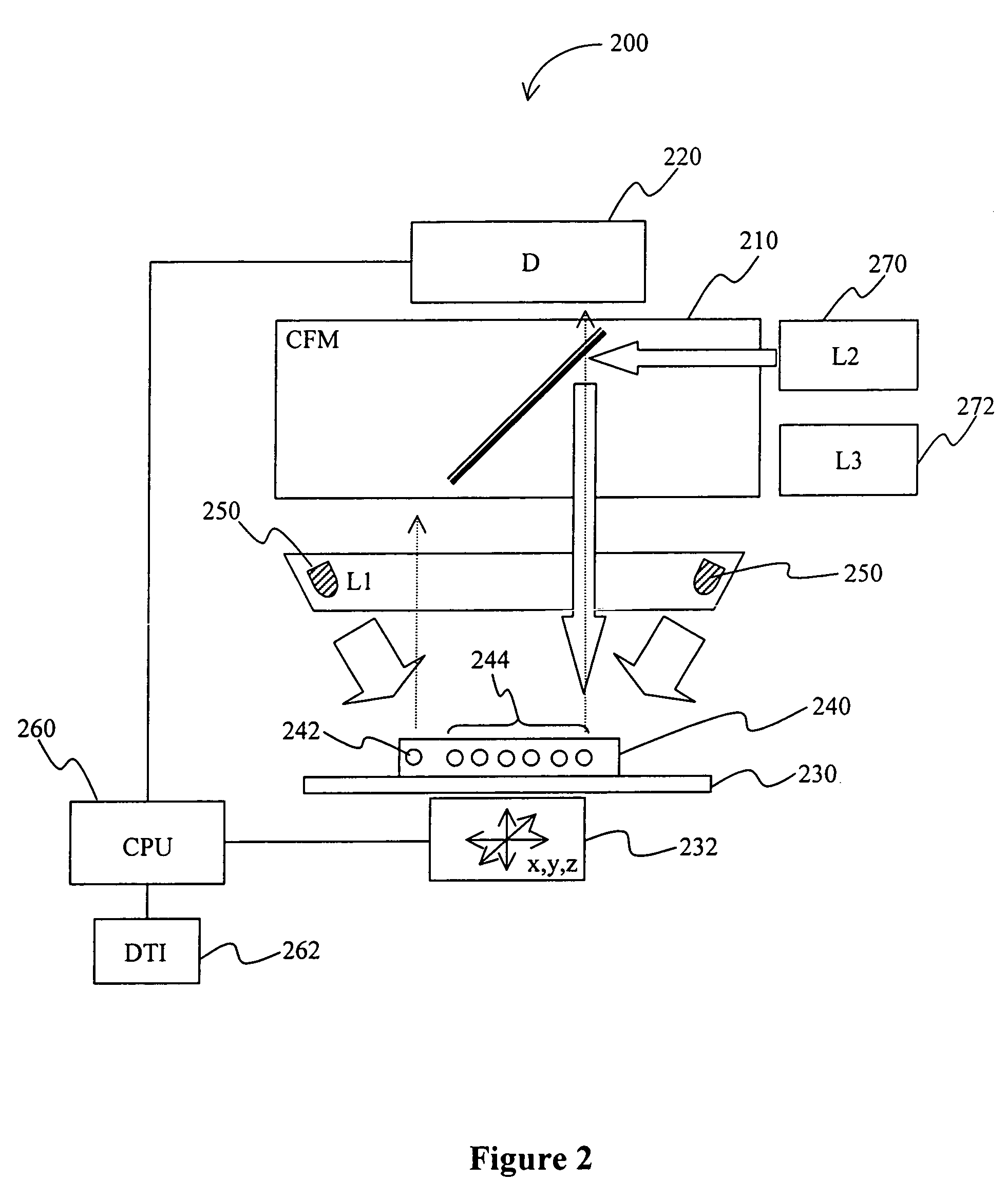
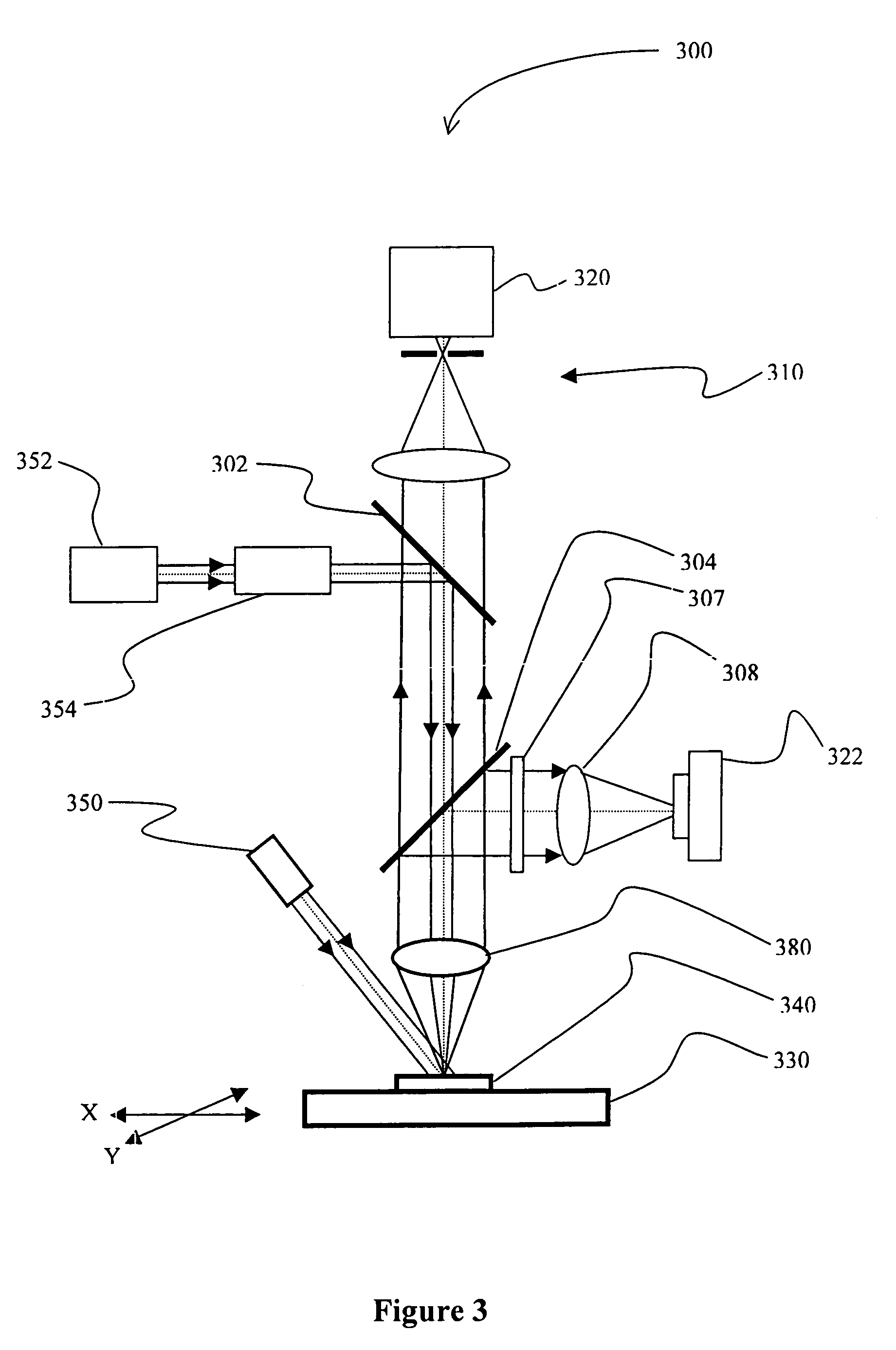
"The present invention is about an analytic system that can detect multiple analytes on a biochip using a first light source to illuminate a registration marker and a second light source to illuminate the analytes. The system uses a platform that moves along x, y, and z coordinates to position the biochip. The first light source illuminates the registration marker, and the second light source illuminates the analytes. The system uses registration markers that have different wavelength maximums than the absorption maximum of the optically detectable label on the analytes. The registration markers and the analytes can be illuminated at different angles, and the system can include a data transfer interface to transfer the data to a computer. The analyte signals have a rounded shape with a diameter of no more than 500 micrometers, and the test result is calculated from the average or integrated signal value of a portion of the round shape. The system can also include a third light source to illuminate the analyte to generate a second analyte signal. The technical effects of the invention include improved accuracy and sensitivity in detecting multiple analytes on a biochip and improved data transfer capabilities."

Problems solved by technology

With the advent of high-throughput screening of small-molecule, nucleic acid, and polypeptide arrays, new challenges have arisen to provide accurate and fast data acquisition.
While such systems are advantageous in various respects, several difficulties remain.
For example, the quantification range for determination of hybridized molecules is at least in some circumstances less than desirable.
Furthermore, if molecules other than nucleic acids need to be determined electronic detection may not be available or technically feasible.
Still further, electronic detection is relatively expensive and poses at least some difficulties where a user wants to customize an array.
However, regardless of the particular excitation-type, numerous problems associated with scanner-based detection remain.
Most significantly, the illuminated array is frequently not positioned at the same distance relative to the detector (e.g., the array is warped, or has a surface unevenness), typically resulting in inaccurate detection of the signal.
However, such focusing mechanism would likely significantly reduce the speed at which the scanner would acquire data.
Moreover, by exposing non-analyzed analytes to illumination conditions for prolonged periods of time, photobleaching of the labels will most likely result in inaccuracies of the later obtained test results.
However, while such systems typically provide relatively accurate data, the time required for focusing the detection optics on a spot-by-spot basis increases with increasing array size.
Thus, even with relatively small arrays (e.g., 50 to 100 probes), detection time tends to become unacceptable, especially where high-throughput screening is desired.
Thus, although various systems for optical detection of signals from microarrays are known in the art, numerous problems still remain.

Method used


Image

  • Microarray detector and methods
  • Microarray detector and methods
  • Microarray detector and methods

Examples


Embodiment Construction

[0020]As used herein, the term “biochip” generally refers to a carrier that has a plurality of probes (to which an analyte may be coupled) in predetermined positions. In especially preferred biochips, at least one of the probes is coupled to the carrier via a crosslinker that is disposed in a matrix, and exemplary multi-substrate chips are described in commonly-owned and copending U.S. patent application Ser. No. 10 / 346,879, filed Jan. 17, 2003, and the PCT applications with the Ser. Nos. PCT / US02 / 03917, filed Jan. 24, 2002, and PCT / US01 / 47991, filed Dec. 11, 2001, all of which are incorporated by reference herein.

[0021]The term “predetermined position” of an analyte refers to a particular position of the analyte on the chip that is addressable by at least two coordinates relative to a registration marker on the chip, and particularly excludes a substantially complete coating of the chip with the analyte an / or probe. Therefore, preferred pluralities of predetermined positions will i...


PUM

PropertyMeasurementUnit
diameteraaaaaaaaaa
diameteraaaaaaaaaa
temperatureaaaaaaaaaa

Abstract

A detector for optical analysis of a biochip determines the focal position of a plurality of analytes on the biochip using one or more registration markers on the biochip, wherein the analytes and the registration marker are illuminated by different light sources. Therefore, contemplated configurations will significantly reduce overall focusing time and automate proper positioning of the biochip, while allowing to determine a focal position without photobleaching or other undesirable effects on optically labile compounds. Thus, automated analyses can be performed without manual user intervention.

Description

[0001]This application claims the benefit of U.S. provisional patent application with the Ser. No. 60 / 383,896, filed May 28, 2002, and international patent application with the Ser. No. PCT / US02 / 17006, filed May 29, 2002, both of which are incorporated herein by reference.FIELD OF THE INVENTION[0002]The field of the invention is optical detection, and especially as it relates to signal detection from an array with bound analytes.BACKGROUND OF THE INVENTION[0003]With the advent of high-throughput screening of small-molecule, nucleic acid, and polypeptide arrays, new challenges have arisen to provide accurate and fast data acquisition. Depending on the type of array, numerous configurations and methods for data acquisition are known in the art.[0004]For example, arrays can be electronically queried to detect hybridization of a nucleic acid sample to an immobilized probe of a probe array, typically allowing an operator to obtain a relatively high number of data in relatively short time...

Claims


Application Information

Patent Timeline
Patent Type & Authority Patents(United States)
IPC IPC(8): C40B60/08G01N21/25G01N21/64G01N35/00G01N35/10
CPCG01N21/253G01N21/6428G01N21/6452G01N35/00732G01N35/1016B01J2219/00576B01J2219/00659B01J2219/00702G01N2035/00158G01N2035/00673G01N2035/00782G01N2035/1025
Inventor KURESHY, FAREEDMAHANT, VIJAY K.SINGH, SHAILENDRASHEN, XIAOHUA
Owner AUTOGENOMICS
Learn More