Endoscopic imaging system and endoscope system

an endoscope and imaging system technology, applied in the field of endoscope system and endoscope system, can solve the problems of complex circuitry, difficult to precisely operate the pll, complex circuitry in the image processing unit (or video processing unit), etc., and achieve the effect of simplifying the configuration of the video processing uni

Inactive Publication Date: 2008-04-08
OLYMPUS CORP
View PDF12 Cites 94 Cited by
  • Summary
  • Abstract
  • Description
  • Claims
  • Application Information

AI Technical Summary

Benefits of technology

[0020]Even when the signal transmission line has different lengths, the phase adjustment circuit incorporated in the imaging apparatus linked to the signal transmission line precisely adjusts the phases of the driving signals output fro

Problems solved by technology

A problem with the Japanese Unexamined Patent Publication No. 6-86138 lies in that the PLL is used to adjust the phases of signals and produce various timing pulses in effort to make corrections for cables of different lengths.
This makes the circui

Method used


Image

  • Endoscopic imaging system and endoscope system
  • Endoscopic imaging system and endoscope system
  • Endoscopic imaging system and endoscope system

Examples


first embodiment

[0055]The first embodiment of the present invention will be described with reference to FIG. 1 to FIG. 7D.

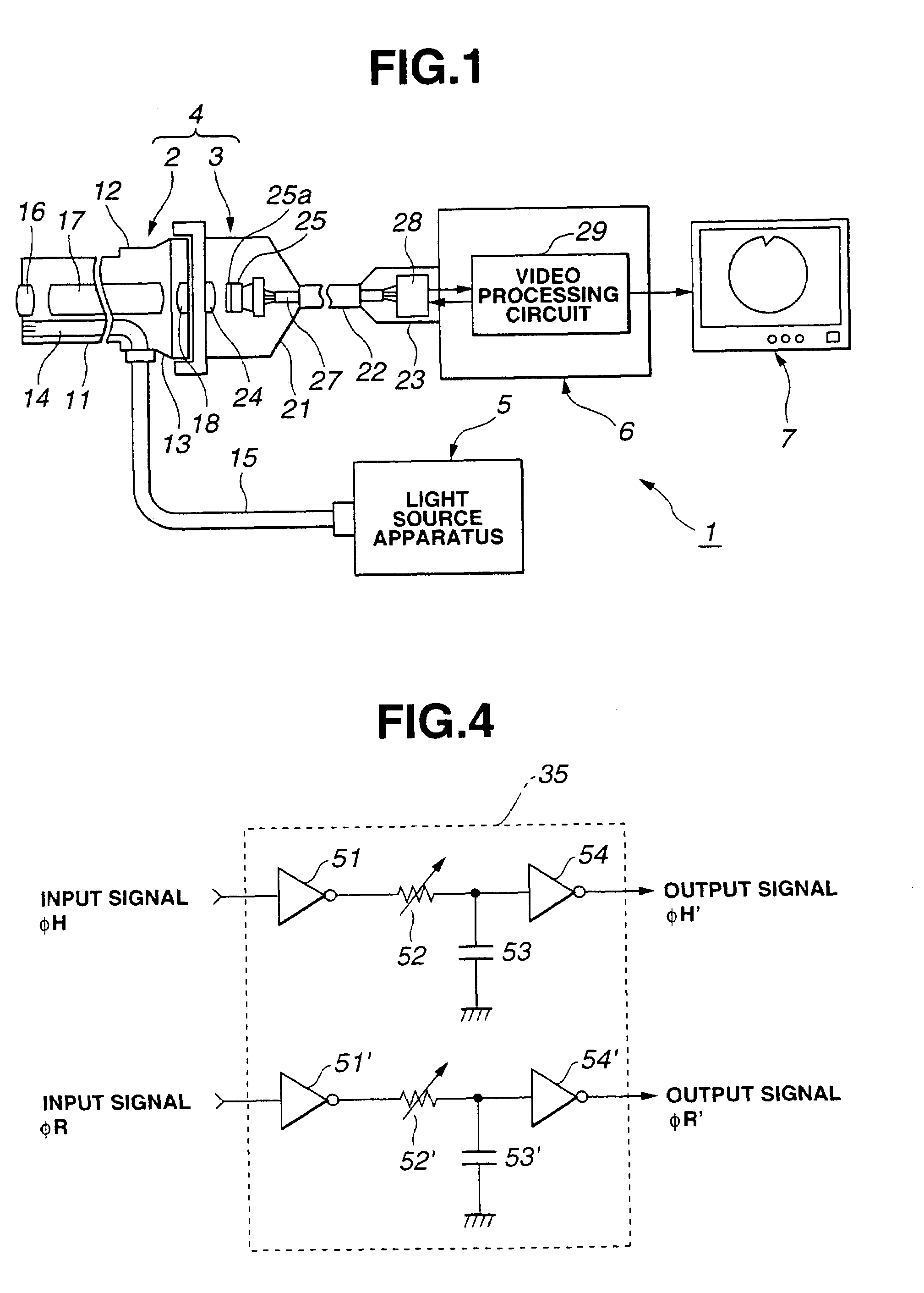
[0056]As shown in FIG. 1, an endoscopic imaging system 1 in accordance with the first embodiment of the present invention consists mainly of an endoscope 4 with an external TV camera, a light source apparatus 5, a camera control unit (hereinafter abbreviated to CCU) 6, and a TV monitor 7. The TV-camera mounted endoscope 4 has TV camera 3 (serving as an endoscopic imaging apparatus), which includes an imaging means, mounted on an optical endoscope 2. The light source apparatus 5 supplies illumination light to the optical endoscope 2. The CCU 6 is removably connected to the TV camera 3 so that it can be disconnected freely. The CCU 6 processes a video signal to produce a standard video signal. The TV monitor 7 displays endoscopic images according to the video signal output from the CCU 6.

[0057]The optical endoscope 2 is a rigid endoscope having, for example, a rigid insertion unit...

second embodiment

[0129]Next, the second embodiment of the present invention will be described with reference to FIG. 8 to FIG. 13.

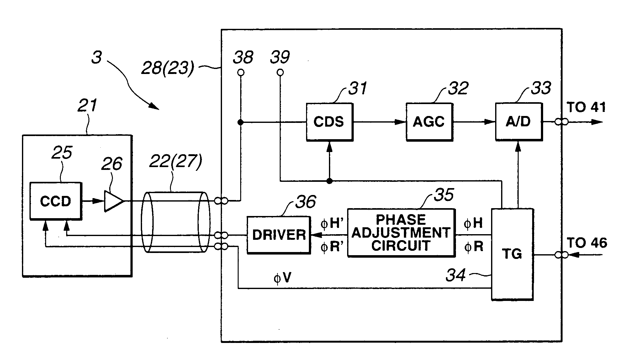
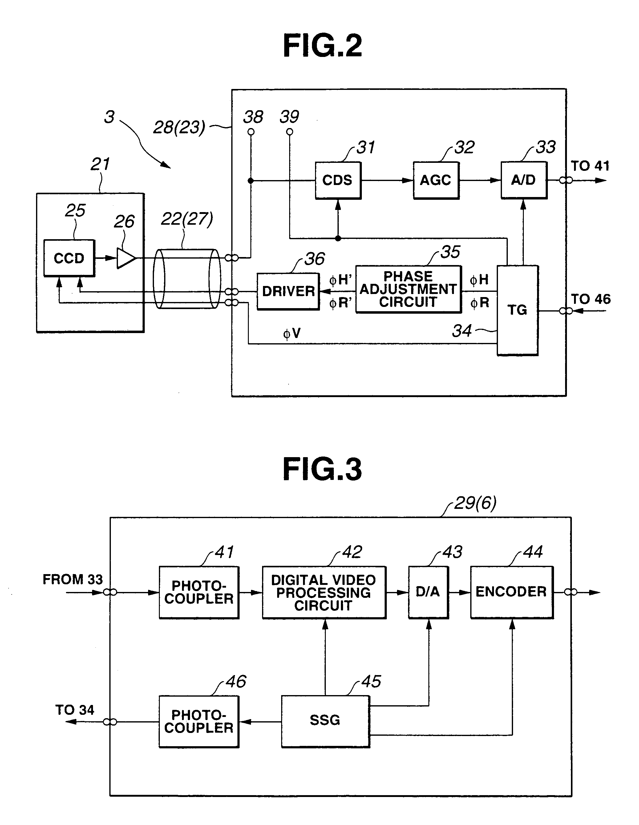
[0130]The present embodiment is different from the first embodiment in the configuration of the pre-processing circuit 28 shown in FIG. 2. That is to say, an electronic voltage regulator (hereinafter abbreviated to an EVR) 80 is connected to the phase adjustment circuit 35 (see FIG. 8). A control signal is supplied from an EVR setting circuit 81 included in the video processing circuit 29 in the CCU 6 shown in FIG. 9 to the EVR 80.

[0131]An input signal of the CDS circuit 31 and sampling pulses output from the timing generator 34 are input to the video processing circuit 29 in the CCU 6. The waveforms of the signals can be observed at test pins 82 and 83 in the video processing circuit 29.

[0132]FIG. 10 shows the configuration of the phase adjustment circuit 35 in accordance with the present embodiment. The phase adjustment circuit 35 is different from the phase adjustment ...

third embodiment

[0146]Next, the third embodiment of the present invention will be described with reference to FIG. 14 to FIG. 18. The present embodiment is constructed by modifying and improving the first embodiment.

[0147]An endoscopic imaging system 1′ shown in FIG. 14 is different from the endoscopic imaging system 1 shown in FIG. 1 in the points described below. Namely, a processing circuit (driving adjustment circuit) 28′ whose configuration is partly different from that of the pre-processing circuit 28 incorporated in the connector 23 is substituted for the pre-processing circuit 28. A video processing circuit 29′ whose configuration is partly different from that of the video processing circuit 29 incorporated in the CCU 6 shown in FIG. 1 is substituted for the video processing circuit 29. These components different from the counterparts employed in the first embodiment will be specifically described below.

[0148]FIG. 15 shows the electric configuration of the TV camera 3. The electric configur...


PUM


Abstract

An imaging apparatus having an imaging device for imaging an object in cooperation with an endoscope is connected to a video processing unit for producing a standard video signal so that it can be disconnected freely. A signal delay occurs over a signal line linking the imaging device and the video processing unit. For this reason, a timing generator and a phase adjustment circuit are incorporated in the imaging apparatus. The timing generator generates driving signals used to drive the imaging device, and the phase adjustment circuit adjusts the phases of the driving signals so that an output signal of the imaging device will be input to the video processing unit according to predetermined timing. Even when the signal line has a different length from any other or the imaging device offers a different number of pixels from any other, the difference can be readily coped with owing to the imaging apparatus. This leads to alleviation of a load incurred by the video processing unit.

Description

BACKGROUND OF THE INVENTION[0001]1. Field of the Invention[0002]The present invention relates to an endoscopic imaging system and an endoscope system for producing endoscopic images.[0003]2. Description of the Related Art[0004]In recent years, endoscopes have been widely adopted in the fields of medicine and industries. Recently, an endoscopic imaging system having an endoscopic imaging apparatus for producing endoscopic images has come to be used widely. For example, Japanese Unexamined Patent Publication No. 6-86138 has disclosed a related art.[0005]According to the related art, since a signal delay occurs over a cable linking an imaging device and an image processing unit (or video processing unit), a correction needs to be made for cables having different lengths. For this purpose, a reference signal is produced using an output signal of a charge coupled device (CCD). A phase-locked loop (PLL) composed of a phase adjustment circuit, a low-pass filter (LPF), and a voltage-control...

Claims


Application Information

Patent Timeline
IPC IPC(8): H04N7/18
CPCA61B1/042H04N5/232H04N7/183H04N2005/2255H04N23/555H04N23/60
Inventor MOCHIDA, AKIHIKOSAITO, KATSUYUKITASHIRO, HIDEKIOGASAWARA, KOTAROTSUNAKAWA, MAKOTOKUSAMURA, NOBORU
Owner OLYMPUS CORP
Why Eureka
Try Eureka