Liquid crystal device, its driving method, and driving apparatus

a liquid crystal device and driving method technology, applied in static indicating devices, instruments, record information storage, etc., can solve the problems of liquid crystal damage, degradation in the quality of playback signals, and increase the occurrence of read errors

Inactive Publication Date: 2008-04-08
SONY CORP
View PDF6 Cites 0 Cited by
  • Summary
  • Abstract
  • Description
  • Claims
  • Application Information

AI Technical Summary

Benefits of technology

[0019]According to the present invention, the first to fourth driving signals are applied to the first to sixth electrode portions of the liquid crystal, thus allowing a voltage to be individually applied to liquid crystal portions between the first to sixth electrode portions. Therefore, the phase differences between the driving signals are adjusted, thereby controlling an effective voltage to be applied to the liquid crystal to independently control the refractive index of the liquid crystal portions.

Problems solved by technology

If the optical disk is inclined, or tilted (skewed), with respect to the light beam emitted from the optical head onto the optical disk, a spatial phase shift occurs in the playback laser beam spot, thus causing degradation in quality of the playback signals while increasing the occurrence of read errors.
Generally, liquid crystals are damaged when a DC voltage (direct-current voltage) is applied.
Therefore, there is a problem with the related art in that a complex method and apparatus for driving a liquid crystal device must be used to adjust the refractive index of the liquid crystal device, thus increasing the cost.

Method used


Image

  • Liquid crystal device, its driving method, and driving apparatus
  • Liquid crystal device, its driving method, and driving apparatus
  • Liquid crystal device, its driving method, and driving apparatus

Examples


first embodiment

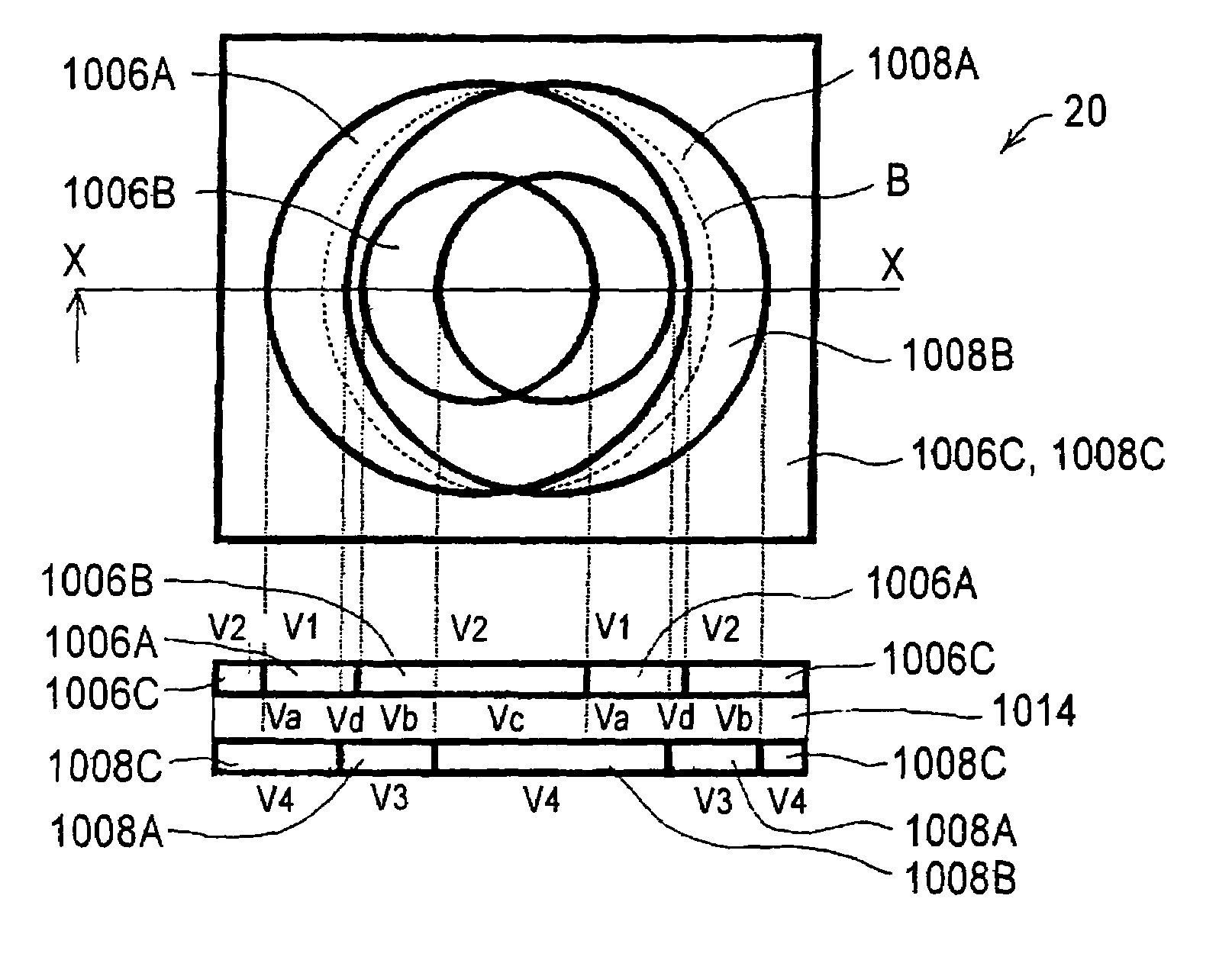
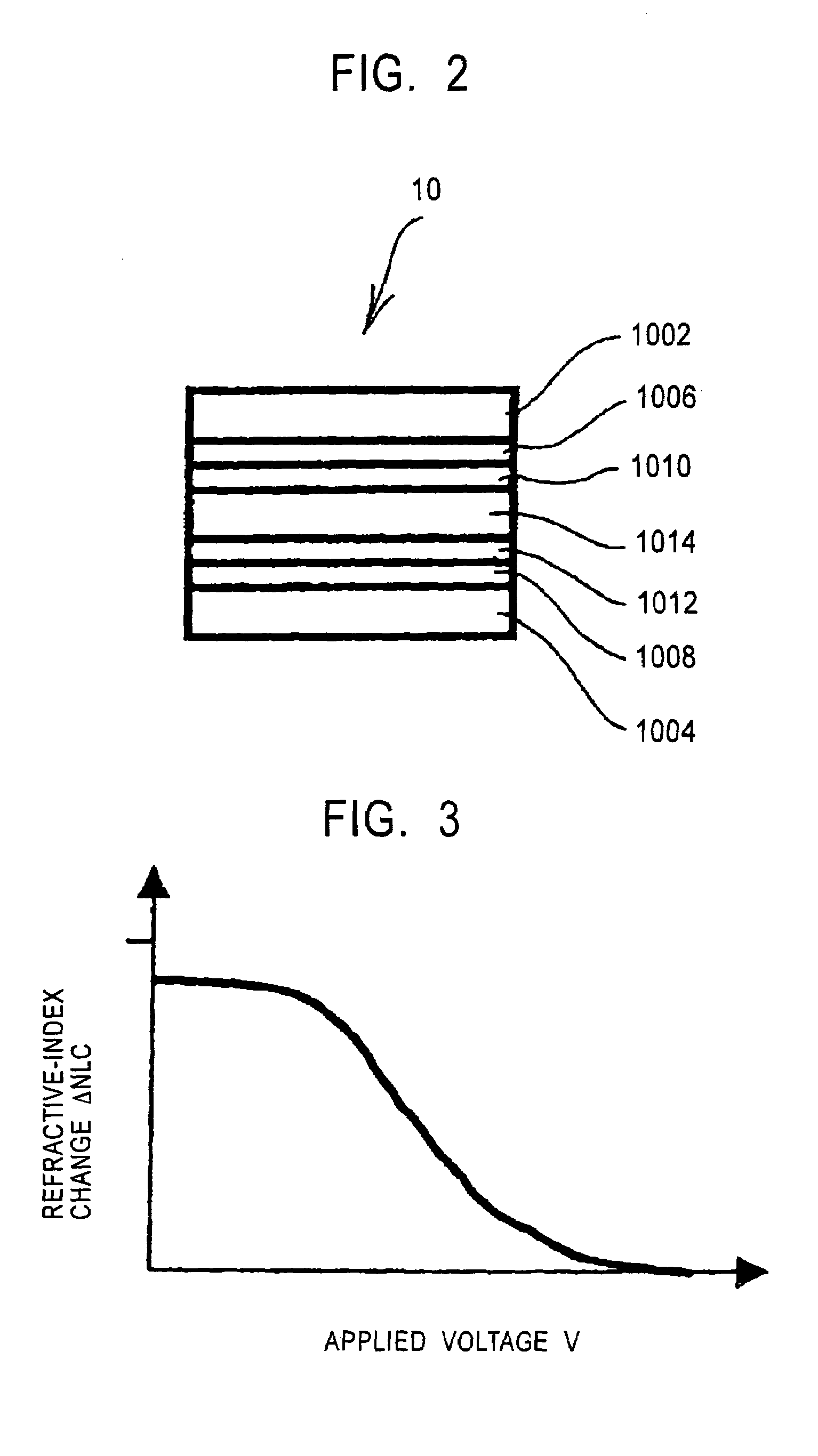
[0038]FIG. 2 is a diagram showing the structure of a liquid crystal device according to the present invention.

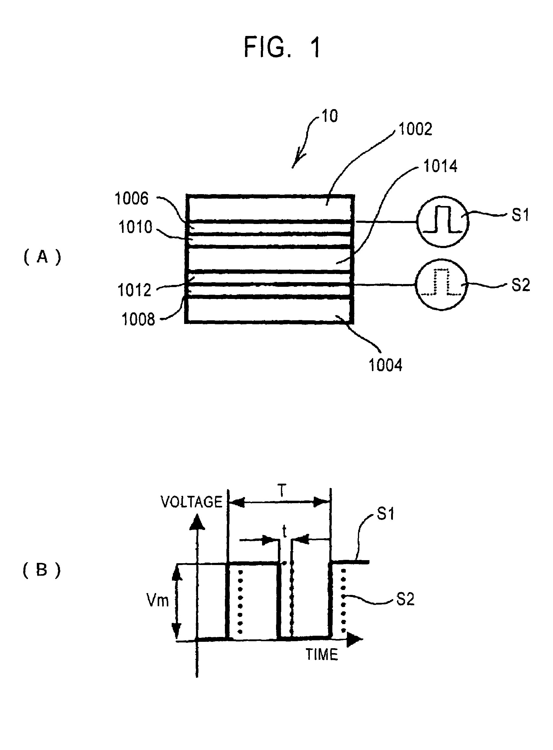
[0039]A liquid crystal device 10 includes a first transparent substrate 1002 and a second transparent substrate 1004 that face each other, a liquid crystal 1014 filled between the first and second transparent substrates 1002 and 1004, a first transparent electrode 1006 formed on a surface of the first transparent substrate 1002 that faces the second transparent substrate 1004, a second transparent electrode 1008 formed on a surface of the second transparent substrate 1004 that faces the first transparent substrate 1002, an alignment film 1010 formed on a surface of the first transparent electrode 1006 that faces the second transparent electrode 1008, and an alignment film 1012 formed on a surface of the second transparent electrode 1008 that faces the first transparent electrode 1006.

[0040]The first and second transparent substrates 1002 and 1004 are placed in parallel to ea...

second embodiment

[0072]A second embodiment will now be described.

[0073]The second embodiment will be described in the context of a liquid crystal device for compensating for a phase shift caused when an optical disk is tilted, and a method and an apparatus for driving the liquid crystal device.

[0074]First, the necessity for compensation of a phase shift caused due to tilting of an optical disk will be described.

[0075]When a recording surface of an optical disk is tilted with respect to a light beam emitted from an optical head onto the recording surface, that is, when there is an angle between the light beam and the axis orthogonal to the recording surface, the capability of focusing a beam spot onto the disk recording surface through a transparent disk substrate of the optical disk is degraded.

[0076]This is because the light beam passing through the tilted transparent disk substrate experiences an aberration in the spatial phase distribution of the light beam, i.e., a wavefront aberration.

[0077]Thu...

third embodiment

[0131]A third embodiment will now be described.

[0132]The third embodiment is different from the second embodiment in that driving signals are controlled so that the envelope (amplitude) of an RF signal obtained by playback of a recording signal recorded in an optical disk becomes the maximum. That is, the envelope (amplitude) of the RF signal is maximum, resulting in no tilt error.

[0133]FIG. 16 is a circuit diagram showing a control system of a driving apparatus for a liquid crystal device according to the third embodiment. Components similar to those of the second embodiment shown in FIG. 15 are given the same reference numerals, and a description thereof is omitted.

[0134]As shown in FIG. 16, in a driving apparatus 2000, an RF signal detected by the photodetector 3018 described above is amplified by a buffer amplifier 2024 and an automatic gain control amplifier 2026.

[0135]The gain of the automatic gain control amplifier 2026 is automatically switched by a gain switch 2036 to a fix...


PUM

PropertyMeasurementUnit
transparentaaaaaaaaaa
square-wave voltageaaaaaaaaaa
voltage amplitude V1aaaaaaaaaa

Abstract

A liquid crystal device, and a method and an apparatus for driving the same in which the refractive index of the liquid crystal device is adjusted using a simple driving method and apparatus, which is advantageous in that the cost is reduced, are provided. A liquid crystal device (10) includes a first transparent substrate (1002) and a second transparent substrate (1004) that face each other, a liquid crystal (1014) filled between the first and second transparent substrates (1002, 1004), a first transparent electrode (1006) formed on a surface of the first transparent substrate (1002) that faces the second transparent substrate (1004), and a second transparent electrode (1008) formed on a surface of the second transparent substrate (1004) that faces the first transparent substrate (1002). First and second driving signals (S1, S2) of square waves are applied to the first and second transparent electrodes (1002, 1004) with a time interval t (sec) therebetween. Thus, the potential difference between the first and second driving signals (S1, S2) is applied to the liquid crystal (1014).

Description

TECHNICAL FIELD [0001]The present invention relates to a liquid crystal device, and a method and an apparatus for driving the same.BACKGROUND ART [0002]Typically, in playing back a signal recorded on an optical disk having a land / groove format using an optical head, the playback laser beam from the optical head experiences an optical phase difference between playback in a land and playback in a groove. Thus, the optical head requires optical compensation equipment for removing the optical phase difference in order to increase the quality of both playback signals for the land and the groove.[0003]If the optical disk is inclined, or tilted (skewed), with respect to the light beam emitted from the optical head onto the optical disk, a spatial phase shift occurs in the playback laser beam spot, thus causing degradation in quality of the playback signals while increasing the occurrence of read errors. Thus, a compensator for compensating for such a phase shift, or an optical phase differ...

Claims


Application Information

Patent Timeline
Patent Type & Authority Patents(United States)
IPC IPC(8): G11B7/00G02F1/13G02F1/133G11B7/007G11B7/095G11B7/135G11B7/1369G11B7/1392
CPCG02F1/13306G11B7/13927G11B7/0956G11B7/1369G11B7/00718G02F2201/122G02F2203/50G02F1/13
Inventor TAKESHITA, YASUYUKIFUKUMOTO, ATSUSHIKAI, SHINICHI
Owner SONY CORP
Why Eureka
Try Eureka