System and method supporting auto-recovery in a transceiver system

a transceiver and auto-recovery technology, applied in the field of automatic recovery within the transceiver chip, can solve the problem that the system level reset process may take an undesirably long tim

Inactive Publication Date: 2008-04-08
AVAGO TECH INT SALES PTE LTD
View PDF9 Cites 8 Cited by
  • Summary
  • Abstract
  • Description
  • Claims
  • Application Information

AI Technical Summary

Benefits of technology

[0019]Certain embodiments of the present invention provide a method and apparatus to aid a transceiver chip in recovering from a system-side, out-bound data clocking problem.

Problems solved by technology

The system level reset process may take an undesirably long time and corrupted data may be transmitted out of the line-side of the outbound section of the transceiver chip.

Method used


Image

  • System and method supporting auto-recovery in a transceiver system
  • System and method supporting auto-recovery in a transceiver system
  • System and method supporting auto-recovery in a transceiver system

Examples


Embodiment Construction

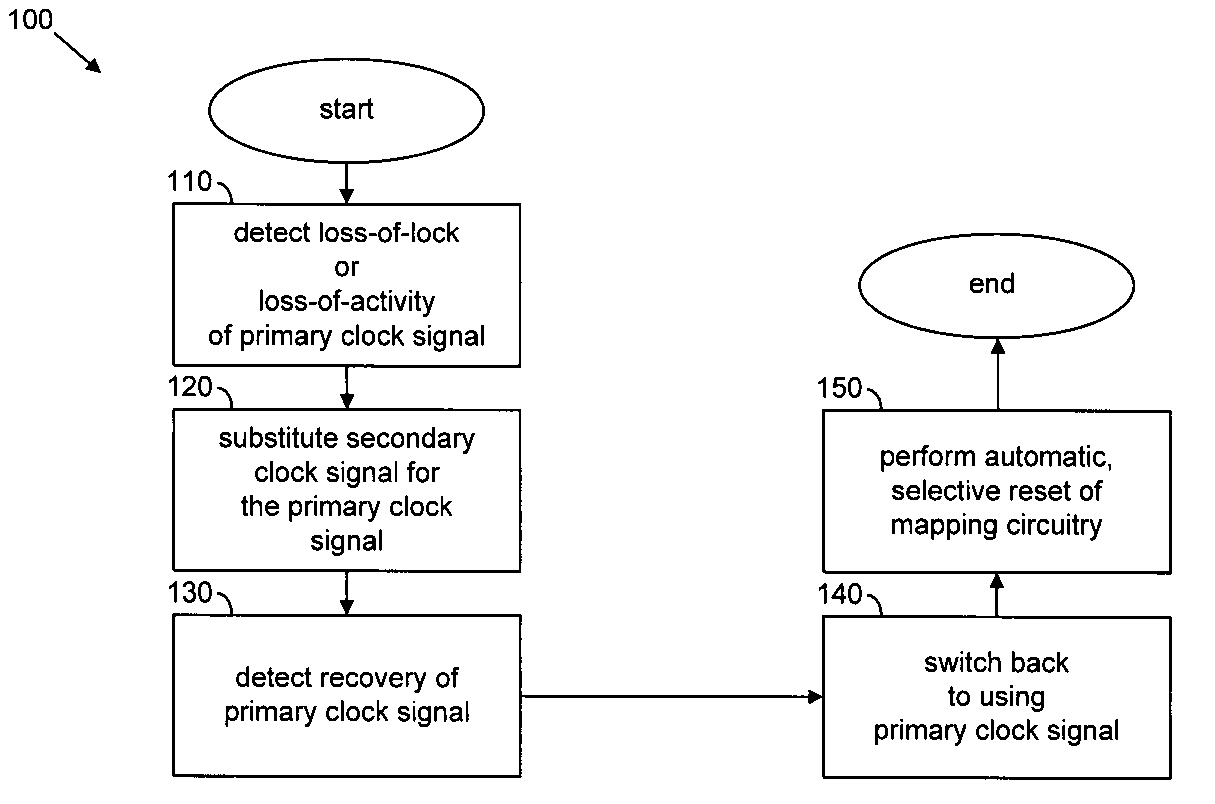
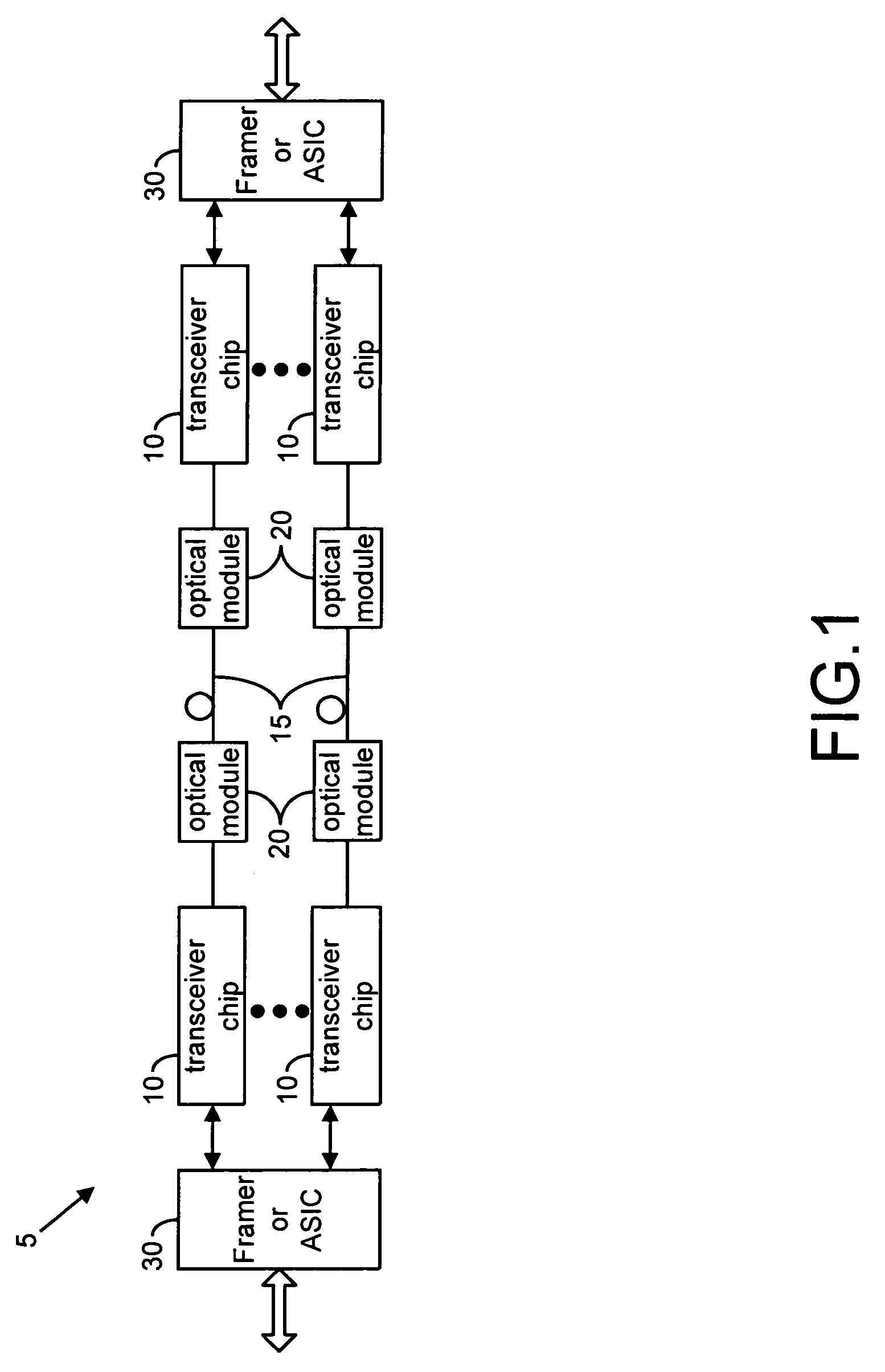
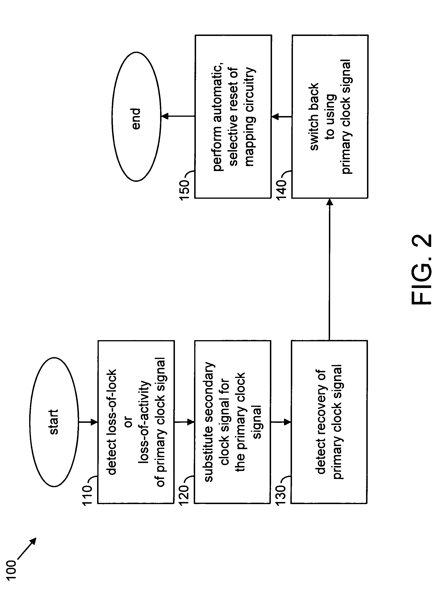
[0028]FIG. 1 is a schematic block diagram of part of an optical serial data communications system 5 using transceiver chips 10 in accordance with an embodiment of the present invention. The communications system 5 shows optical fiber 15 linking optical modules 20. The optical modules transmit and receive optical serial data over the optical fiber 15 and convert the optical serial data to electrical serial data and vice versa.

[0029]The transceiver chips 10 interface to the optical modules 20 on the line-side to transmit and receive electrical serial data to and from the optical modules 20. The transceiver chips 10 perform various communications functions including clock data recovery (CDR), clock generation, data de-serialization and serialization, synchronization, data decoding and encoding, and transmission and reception of bit streams in accordance with an embodiment of the present invention. The transceiver chips 10 interface to a Framer or ASIC 30 on the system-side to format, t...


PUM


Abstract

A method and apparatus are disclosed to aid a transceiver chip, in a serial data communications system, in recovering from a system-side, out-bound data clocking problem. If a problem with a primary clock signal, used to clock data from a system-side of a transceiver chip through at least a part of an out-bound data path of the transceiver chip, is detected, then a more reliable secondary clock signal is substituted for the primary clock signal. Once it is determined that the primary clock signal has recovered, the primary clock signal is switched back to and certain discrete circuits of the out-bound data path of the transceiver chip are automatically reset in hardware without the need for system level intervention to avoid any problems due to clock glitches on the primary clock signal during the switching.

Description

CROSS-REFERENCE TO RELATED APPLICATIONS / INCORPORATION BY REFERENCE[0001]Each of the following applications are related to the present application and are incorporated herein by reference in their entirety:[0002]Ser. No.TitleDocket No.FiledInventor(s):60 / 423,070Transceiver System and14103US01Nov. 01, 2002VikramMethod SupportingNatarajan, KangVariable Rates andXiao, MarioMultiple ProtocolsCaresosa, JayProano60 / 423,166Method and System for14104US01Nov. 01, 2002Chenmin Zhang,a Three ConductorSteve Thomas,Transceiver BusRandall Stolaruk60 / 423,034Multi-Rate On-Chip14107US01Nov. 01, 2002Ichiro Fujimori,OCN Filter for aMario Caresosa,Transceiver SystemNamikKocaman60 / 423,071Method and System for14106US01Nov. 01, 2002Jay Proano,Synchronizing aSheila Qiu, TimTransceiver and aChan, HongtaoDownstream Device inJiangan OpticalTransmission Network60 / 423,072Transceiver System and14108US01Nov. 01, 2002Mario Caresosa,Method SupportingNamikMultiple SelectableKocamanVCOs60 / 423,074Configurable VCO14109US...

Claims


Application Information

Patent Timeline
Patent Type & Authority Patents(United States)
IPC IPC(8): H04B1/38H04J3/04H04J3/06H04Q11/04
CPCH04J3/04H04J3/0685H04J3/0688H04J2203/0089
Inventor XIAO, KANGCARESOSA, MARIOJIANG, HONGTAOSTOLARUK, RANDALL
Owner AVAGO TECH INT SALES PTE LTD
Why Eureka
Try Eureka