Flash tank of two-stage compression heat pump system for heating and cooling

a heat pump system and two-stage technology, applied in the direction of heat pumps, lighting and heating apparatus, machine operation modes, etc., can solve the problems of reducing the heating capacity, heating energy consumption, and reducing the operating efficiency of the compressor

Active Publication Date: 2008-04-15
KOREA INST OF ENERGY RES
View PDF10 Cites 9 Cited by
  • Summary
  • Abstract
  • Description
  • Claims
  • Application Information

AI Technical Summary

Benefits of technology

[0008]Therefore, the present invention has been made in view of the above problems occurring in the prior art, and it is an object of the present invention to provide a two-stage compression heat pump system having a flash tank which induces two refrigerants to reach thermal equilibrium smoothly, wherein the refrigerants have different states from each other and flow into the flash tank, to embody a two-stage compression cycle having complete intermediate cooling, to prevent fine droplets from flowing into a high-stage compressor in order to inhibit liquid back or liquid compression in the high-stage compressor, wherein the fine droplets are generated in the process of obtaining thermal equilibrium, and to allow the refrigeration oil flowing into the flash tank together with the refrigerant to be collected into the compressor in order to prevent refrigeration oil from remaining in a specific device so as to extend the life-span and enable stable operations of the device, thereby enhancing system reliability and performance.
[0009]To accomplish the above object, according to one aspect of the invention, there is provided a flash tank of a two-stage compression heat pump system for cooling and heating in one system, having an intercooler that maximizes cooling effect by increasing the degree of sub-cooling of a refrigerant sent to the flash tank and an evaporator, the two-stage compression heat pump system serving to perform a single-stage compression cooling operation in summertime using only a low-stage compressor for stable operations, and using both the low-stage compressor and a high-stage compressor in wintertime for highly efficient operations, wherein the flash tank and the intercooler are separately allocated. The two-stage compression heat pump system comprises: a fluid-level detecting sensor mounted inside the flash tank for detecting a fluid-level of the refrigerant; an alarm sensor for notifying a saturated state of the refrigerant filled in the flash tank; an evaporator pressure sensor for measuring and notifying pressure of the refrigerant flowing into the evaporator; a condenser pressure sensor for measuring and notifying pressure of the refrigerant flowing out of the condenser; a flash tank fluid-level controller for receiving signals from the above sensors and controlling intermediate pressure and the fluid-level of the flash tank; and a bypass valve controller for controlling a bypass valve that receives signals from the alarm sensor, allowing a refrigerant to directly flow from the low-stage compressor to the high-stage compressor. The flash tank comprises: an intercooler outlet pipe mounted on one side of the flash tank; a low-stage compressor outlet pipe mounted on the other side of the flash tank; a high-stage compressor inlet pipe installed inside the flash tank, wherein the high-stage compressor inlet pipe has an end portion of a U-shaped pipe formed at a bottom side of the flash tank, a refrigeration oil inlet provided at a bottom side of the U-shaped pipe, and another end portion connected to the high-stage compressor; and an orifice installed so as to correspond to the refrigeration oil inlet provided at the bottom side of the U-shaped pipe, wherein the orifice is provided for filtering contaminations in the refrigeration oil.
[0010]According to another aspect of the invention, there is also a flash tank of a two-stage compression heat pump system for cooling and heating in one system, having an intercooler that maximizes cooling effect by increasing the degree of sub-cooling of a refrigerant sent to the flash tank and an evaporator, the two-stage compression heat pump system serving to perform a single-stage compression cooling operation in summertime using only a low-stage compressor for stable operations, and using both the low-stage compressor and a high-stage compressor in wintertime for highly efficient operations, wherein the flash tank and the intercooler are separately allocated. The two-stage compression heat pump system comprises: a fluid-level detecting sensor mounted inside the flash tank for detecting a fluid-level of the refrigerant; an alarm sensor for notifying a saturated state of the refrigerant filled in the flash tank; an evaporator pressure sensor for measuring and notifying pressure of a refrigerant flowing into the evaporator; a condenser pressure sensor for measuring and notifying pressure of a refrigerant flowing out of the condenser; a flash tank fluid-level controller for receiving signals from the above sensors and controlling intermediate pressure and the fluid-level of the flash tank; and a bypass valve controller for controlling a bypass valve that receives signals from the alarm sensor, allowing a refrigerant to directly flow from the low-stage compressor to the high-stage compressor. The flash tank comprises: an intercooler outlet pipe mounted on one side of the flash tank; a low-stage compressor outlet pipe mounted on the other side of the flash tank; a helically-shaped pipe connected to the low-stage compressor outlet pipe; a refrigeration oil collecting tube connected to an end portion of the coil-shaped pipe for inducing refrigeration oil into a refrigeration oil tank; a refrigerant vapor discharge port formed at one side of the refrigeration oil collecting tube for discharging refrigerant vapor from the refrigeration oil collecting tube; and a high-stage compressor inlet pipe for inducing refrigerant vapor from the flash tank to the high-stage compressor.
[0012]The two-stage compression heat pump system according to the invention, in a case where the two-stage compressor and the heat pump adopt a separate type intermediate cooling method, induces a stable heat exchange within the flash tank, the heat exchange being performed between the superheated vapor discharged from a low-stage and the refrigerant that has passed through an intercooler, but not turned into a saturated vapor, prevents a liquid back or liquid compression by blocking the droplets generated in the process of heat exchange from flowing into the high-stage compressor, and allows the refrigeration oil mixed with the refrigerant vapor discharged from a low-stage to be easily collected instead of being retained in the flash tank, and thus increases system reliability through device protection, and embodies a two-stage compression cycle with complete intermediate cooling, thereby greatly improving system performance.

Problems solved by technology

However, in the former case where an air conditioner (or a chiller) and an electric heater are assembled in one package, excessive energy is consumed for heating.
Even in the latter case of the heat pump type air conditioner that can save energy, if the temperature of a heat source is decreased in wintertime, such a system operates at an excessive compression ratio together with decreased evaporation pressure, and thus the operating efficiency of the compressor is lowered, and heating capacity is decreased due to the decrease of refrigerant mass flow rate in the system, thereby lowering system efficiency.
In addition, if the evaporation pressure of the system is decreased, the compressor discharge gas temperature can be increased excessively, so that the system can be adversely influenced in terms of safety.
However, conventional flash tanks do not have a device for detecting or removing fine droplets generated in the process of heat balance when refrigerant gas and a two-phase flow state are mixed, where the refrigerant gas is superheated vapor discharged from a low-stage compressor and the two-phase flow refrigerant, passed through an intercooler, has a liquid portion.
Therefore, inflow of the fine droplets into a high-stage compressor cannot be blocked.
Furthermore, an appropriate method of collecting refrigeration oil from the flash tank to the compressor has not been proposed, the refrigeration oil therefore being contained in the refrigerant gas from the low-stage compressor.

Method used


Image

  • Flash tank of two-stage compression heat pump system for heating and cooling
  • Flash tank of two-stage compression heat pump system for heating and cooling
  • Flash tank of two-stage compression heat pump system for heating and cooling

Examples


Embodiment Construction

[0019]Preferred embodiments of the invention will be hereafter described in detail, with reference to the accompanying drawings.

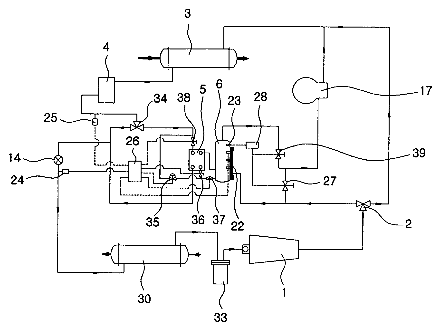
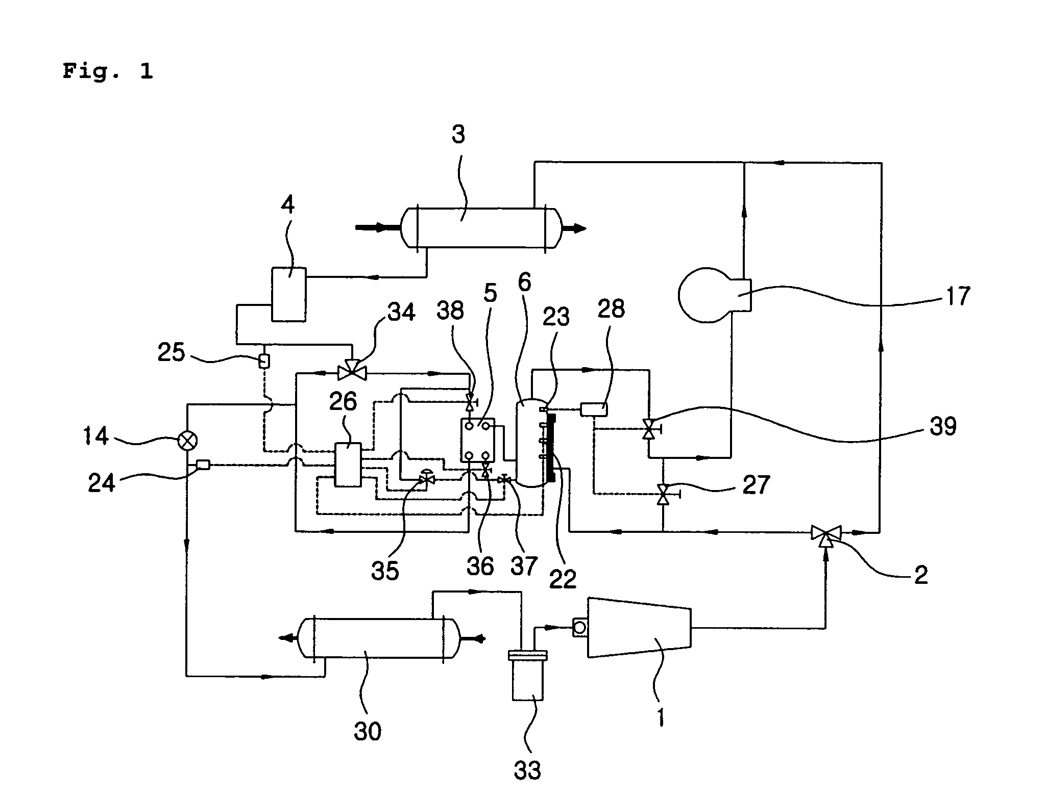
[0020]FIG. 1 schematically shows a two-stage compression heat pump system according to an embodiment of the invention, and FIG. 2 schematically shows a flash tank mounted on the two-stage compression heat pump system according to an embodiment of the invention, which will be explained in detail hereafter. A two-stage compression heat pump system equipped with a flash tank according to the invention is a cooling and heating system that performs cooling and heating in a single unit having an intercooler 5 that maximizes cooling effect by increasing the degree of sub-cooling of refrigerant sent to the flash tank 6 and an evaporator. The two-stage compression heat pump system performs a single-stage compression cooling operation in summertime using only a low-stage compressor 1 for stable operations, and uses both the low-stage compressor 1 and a high-stage com...


PUM


Abstract

Disclosed herein is a flash tank of a two-stage compression heat pump system that can perform cooling and heating with a separate type intercooler and a high-stage compressor protecting device. The system comprises a fluid-level detecting sensor for detecting the fluid-level of the refrigerant, an alarm sensor for notifying the saturated state of the refrigerant filled in the flash tank, an evaporator pressure sensor for measuring and notifying the pressure of the refrigerant flowing into the evaporator, a condenser pressure sensor for measuring and notifying the pressure of the refrigerant flowing out of the condenser, a flash tank fluid-level controller for receiving signals from the above sensors and controlling intermediate pressure and the fluid-level of the flash tank, and a bypass valve controller for controlling a bypass valve that receives signals from the alarm sensor and allowing a refrigerant to directly flow from the low-stage compressor to the high-stage compressor.

Description

CROSS-REFERENCE TO RELATED APPLICATIONS[0001]Priority is hereby claimed to Korean Patent Application Number 10-2005-0001527 filed on Jan. 7, 2005, the entire contents of which are incorporated herein by reference.BACKGROUND OF THE INVENTION[0002]1. Field of the Invention[0003]The present invention relates to a two-stage compression heat pump system adapted to perform cooling and heating in a single unit, which performs a single-stage compressing operation in summertime and a two-stage compressing operation in wintertime, and which has a separate intercooler for controlling the system to provide optimum intermediate pressure, and a device for protecting a high-stage compressor through the control of a fluid-level inside a flash tank.[0004]2. Background of the Related Art[0005]Generally, a conventional system for performing cooling and heating in single unit is either a system having an air conditioner (or a chiller) and an electric heater, or a heat pump type air conditioner having o...

Claims


Application Information

Patent Timeline
Patent Type & Authority Patents(United States)
IPC IPC(8): F25B13/00F25B43/02
CPCF25B1/10F25B31/006F25B29/003F25B43/006F25B2400/13F25B2400/23F25B2600/2501F25B2600/2507F25B2700/04F25B2700/195F25B2700/197F25B29/00F25B30/00
Inventor LEE, YOUNG SOOLEE, WOOK HYUNKIM, JONG RYULJANG, KI CHANGPARK, SEONG RYONGBAIK, YONG JINRA, HO SANG
Owner KOREA INST OF ENERGY RES
Why Eureka
Try Eureka