Drive unit and drive method for press

a technology of drive unit and drive shaft, which is applied in forging presses, forging/pressing/hammering apparatuses, manufacturing tools, etc., can solve the problems of increasing noise when the press touches the workpiece, speed not meeting the desirable forming conditions, and the inability to increase the rotational speed of the slide drive sha

Inactive Publication Date: 2008-04-15
KOMATSU LTD
View PDF11 Cites 12 Cited by
  • Summary
  • Abstract
  • Description
  • Claims
  • Application Information

AI Technical Summary

Benefits of technology

[0017]In the present invention, during the formation phase, processing can be effectively carried out by releasing dynamic energy accumulated in the flywheel and during the non-formation phase, the slide motion can be controlled by the sub motor alone with the flywheel and the main motor being disconnected therefrom, so that acquisition of a great pressuring force and the optimum formation speed during the formation phase is compatible with speeding-up of the slide motion during the non-formation phase.

Problems solved by technology

However, increasing of the rotational speed of the drive shaft causes a proportional increase in the slide speed (i.e., touching speed at which the press touches the workpiece) within the formation zone, which brings about the problem that the resulting speed does not meet the desirable forming conditions.
In addition, noise occurring when the press touches the workpiece increases.
In view of this, the rotational speed of the slide drive shaft cannot be increased so much, and therefore there is a limit to improving productivity.
As a means for solving the above problem, driving of the link mechanism with an electric servo motor is conceivable, but this also reveals such a drawback that a large-sized electric servo motor having larger output torque becomes necessary for generating a pressing force substantially equivalent to a sum of the output torque of the conventional main motor and the accumulating energy of the flywheel.
Use of a large-sized servo motor leads to an increase in the cost and size of the overall press machine.
Furthermore, in cases where a press that has long been in service is modified (i.e., retrofitting), large-scaled reconstruction becomes necessary to replace the conventional main motor with a large-sized electric servo motor, causing problems such as a prolonged reconstruction period and increased reconstruction cost.

Method used


Image

  • Drive unit and drive method for press
  • Drive unit and drive method for press
  • Drive unit and drive method for press

Examples


Embodiment Construction

[0024]Referring now to the accompanying drawings, a press drive unit and a press drive method will be hereinafter described according to an embodiment of the invention.

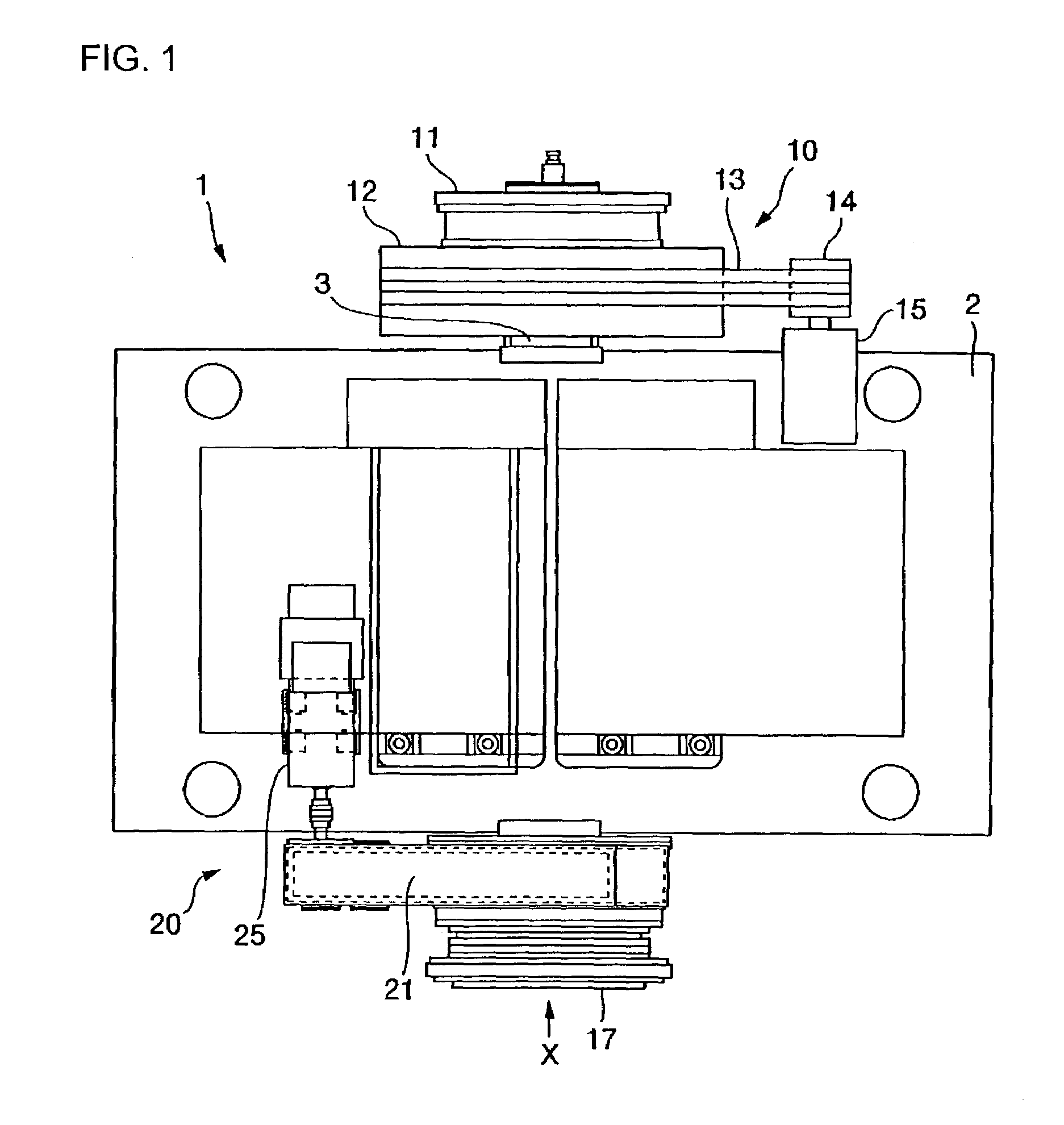
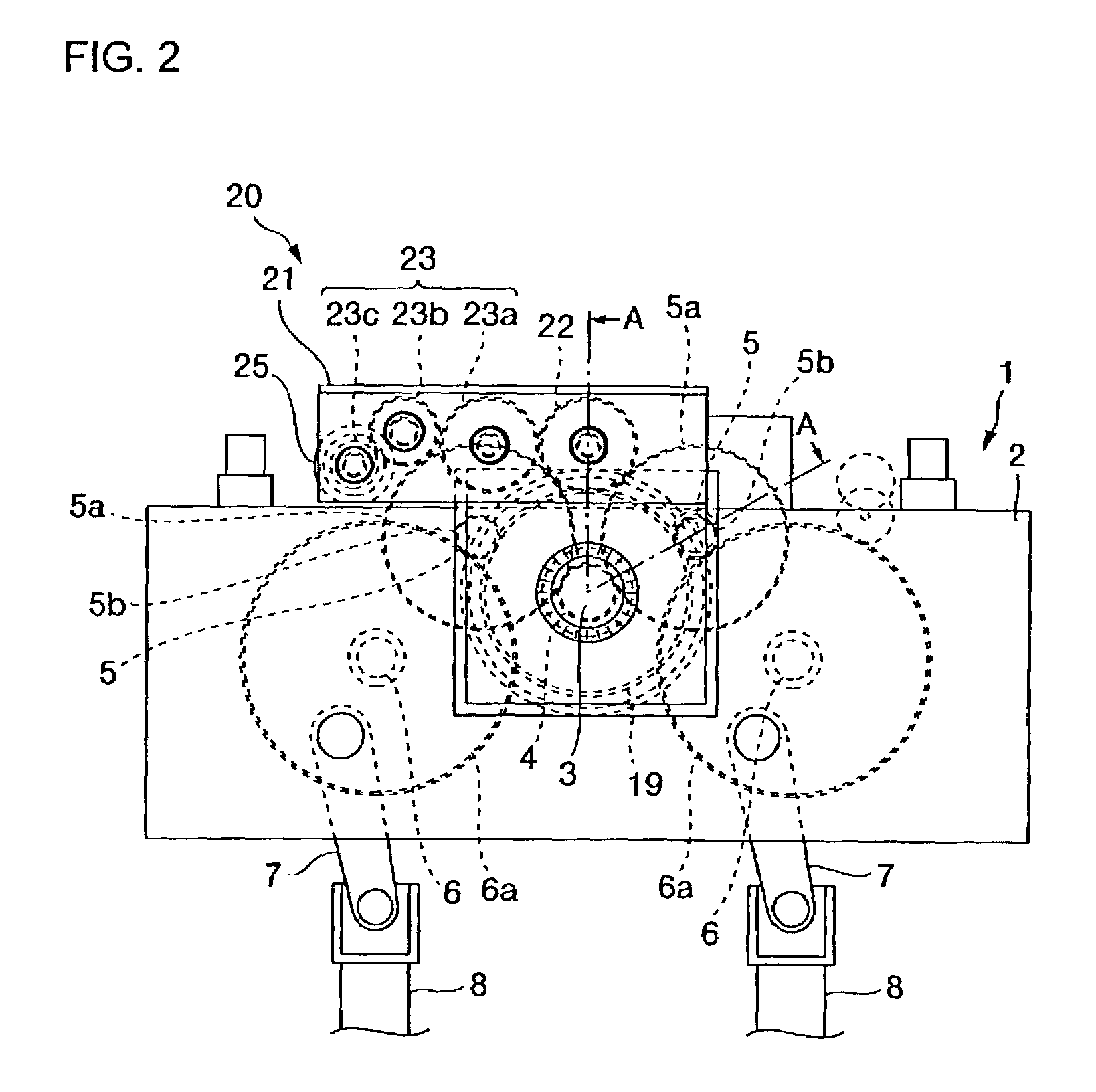
[0025]First, reference is made to FIGS. 1 to 3 to explain the structure of the slide drive unit of a press to which the invention is applied. FIG. 1 is a plan view of a crown of the press. FIGS. 2 and 3 are a view when viewed from X of FIG. 1 and a sectional view taken along line A-A of FIG. 2, respectively.

[0026]According to the present embodiment, disposed within a crown 2 positioned at the upper part of a press 1 is a slide drive unit whose drive shaft 3 is rotatably supported by the frame of the crown 2. At a first end of the drive shaft 3, a first drive system 10 is provided, and at a second end, a second drive system 20 is provided.

[0027]More specifically, a clutch 11 for the drive system 10 is mounted on the first end of the drive shaft 3. The clutch 11 has a drive center 11a which is provided with a facing (no...


PUM

PropertyMeasurementUnit
rotation angleaaaaaaaaaa
speedaaaaaaaaaa
cycle timeaaaaaaaaaa

Abstract

A press drive unit and press drive method are provided which decrease the cycle time of a press to improve its productivity, enable use of small-sized, inexpensive presses and provide improved product quality. To this end, the press drive unit comprises a drive shaft coupled to a slide through a specified power transmission mechanism; a first drive system for rotationally driving a flywheel with a main motor and driving the drive shaft through a clutch disposed between the flywheel and the drive shaft; and a second drive system for driving the drive shaft at variable speed with a sub motor. Driving is carried out with the first and second drive systems in a formation zone, and driving is carried out with the second drive system alone in a non-formation zone.

Description

TECHNICAL FIELD[0001]The present invention relates to a drive unit and drive method for a press which contribute to an improvement in the cycle time of a press.BACKGROUND ART[0002]The slide of a press is generally driven such that it is lowered at low speed conformable to processing conditions within the zone of a forming phase and moved at high speed within other zones than the formation zone, whereby the cycle time of the press is decreased to achieve improved productivity. To obtain such slide motion, there has been conventionally used a link drive press in which the slide is driven by the main motor through a complicated link mechanism. The link mechanism of the link drive press is designed to make the speed of the slide within the formation zone alone (formation speed) slow and to make the speed of the slide within other zones (e.g., lifting phase) than the formation zone a bit faster. The speed difference of the link drive press is up to about 30% of the speed difference of th...

Claims


Application Information

Patent Timeline
Patent Type & Authority Patents(United States)
IPC IPC(8): B30B15/14B21J7/46B30B15/00B30B1/26
CPCB30B1/266B30B15/14B30B15/00
Inventor AOSHIMA, KIYOJI
Owner KOMATSU LTD
Why Eureka
Try Eureka