Method and apparatus for monitoring the condition of a downhole drill bit, and communicating the condition to the surface

a drill bit and condition monitoring technology, applied in the field of downhole failure detection, can solve the problems of poor drilling performance, increased a portion of the drill bit left in the well, and achieve the effects of increasing the wear of the bottom hole assembly, poor drilling performance, and high probability of mechanical failur

Active Publication Date: 2008-04-15
HALLIBURTON ENERGY SERVICES INC
View PDF106 Cites 50 Cited by
  • Summary
  • Abstract
  • Description
  • Claims
  • Application Information

AI Technical Summary

Benefits of technology

[0010]When drilling a well it is desirable to drill as long as possible without wearing the bit to the point of catastrophic bit failure. Optimum bit use occurs when a bit is worn sufficiently that the useful life of the bit has been expended, but the wear is not so extensive that there is a high likelihood of mechanical failure which might result in leaving a portion of the bit in the well. Poor drilling performance, increased BHA (Bottom Hole Assembly) wear, and more frequent fishing jobs all result from continued drilling with bits which are in the process of mechanical failure. A system capable of detecting the early stages of bit failure, with the additional capability of warning the operator at the surface, would be of great value solving the problem of drilling to the point of catastrophic bit failure.
[0011]The innovations in this application provide a reliable, inexpensive means of early detection and operator warning when there is a roller cone drill bit failure. This system is technically and economically suitable for use in low cost rotary land rig drilling operations as well as high-end offshore drilling. The solution is able to detect impending bit failure prior to catastrophic damage to the bit, but well after the majority of the bit life is expended. In addition to failure detection, the innovative system is able to alert the operator at the surface once an impending bit failure is detected.

Problems solved by technology

Optimum bit use occurs when a bit is worn sufficiently that the useful life of the bit has been expended, but the wear is not so extensive that there is a high likelihood of mechanical failure which might result in leaving a portion of the bit in the well.
Poor drilling performance, increased BHA (Bottom Hole Assembly) wear, and more frequent fishing jobs all result from continued drilling with bits which are in the process of mechanical failure.
The first part of the problem is to develop a failure detection method and the second part of the problem is to develop a method to warn the operator at the surface.
The main disadvantage is the necessity of redesigning every bit which will use the method.
In addition to being costly, each new bit design will have to accommodate the embedded sensors which might compromise the overall design.
A second disadvantage arises from the fact that sensor connections and / or data transmission must be made across the threaded connection on the bit to a data processing or telemetry unit.
This is difficult in practice.
Batteries that are suitable for high-temperature, downhole use have the undesirable characteristics of high cost and difficulty of disposal.

Method used


Image

  • Method and apparatus for monitoring the condition of a downhole drill bit, and communicating the condition to the surface
  • Method and apparatus for monitoring the condition of a downhole drill bit, and communicating the condition to the surface
  • Method and apparatus for monitoring the condition of a downhole drill bit, and communicating the condition to the surface

Examples


experimental verification

MSRA Method Experimental Verification

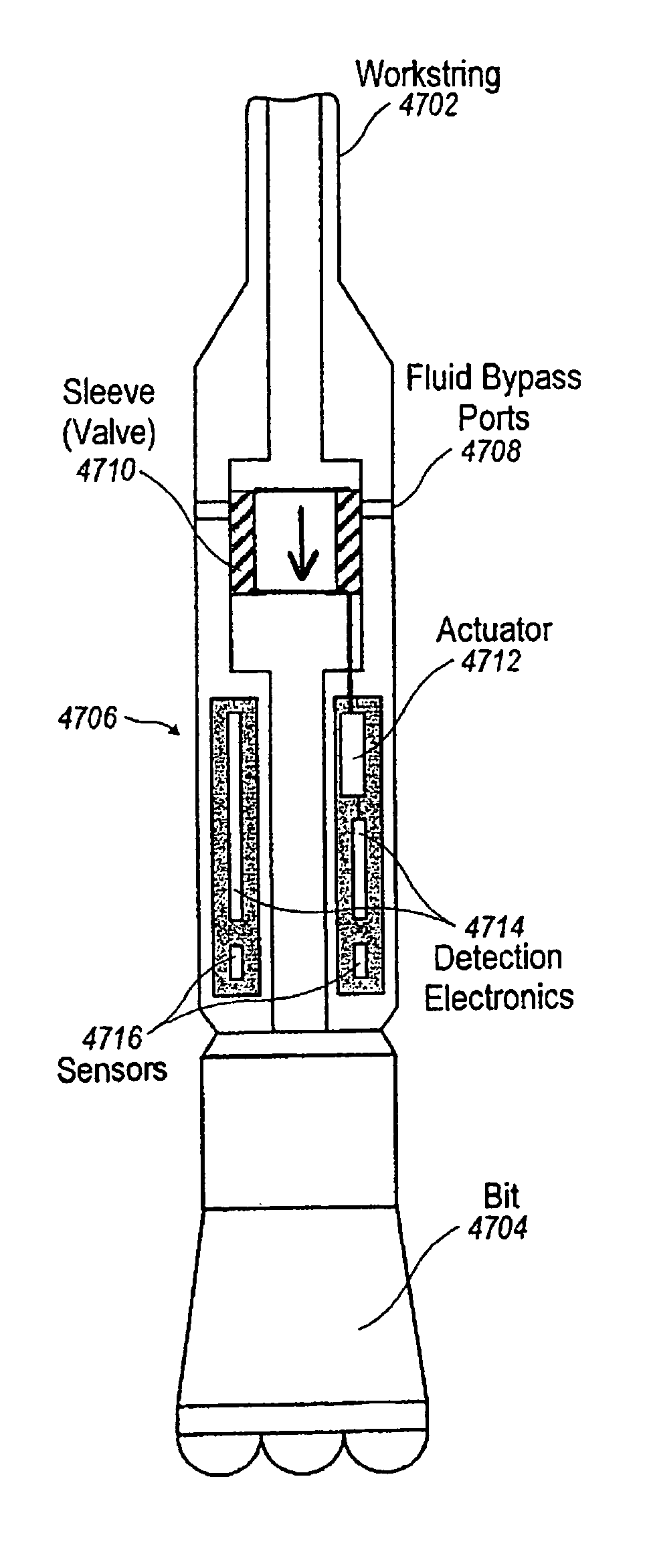
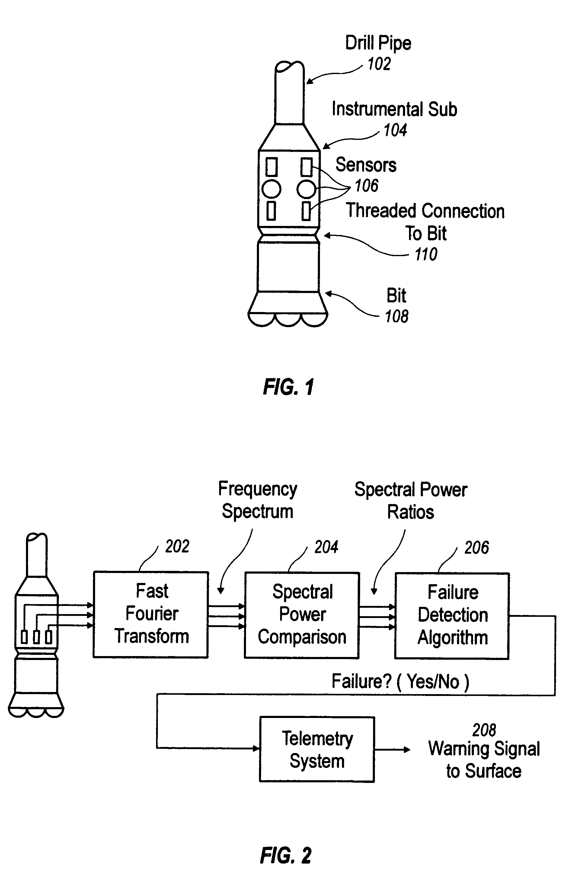
[0148]To verify the validity of the MSRA method, experimental data was collected from a laboratory test of an actual drill bit in operation. In this section the performance results of the MSRA method when applied to experimental data will be presented. Experimental data was collected while using an actual roller cone bit to drill into a cast iron target. Sensors were mounted to a sub directly above the bit and a data acquisition system was used to record the sensor readings. Strain gauges were attached to the sub with 120° phasing directly above the bit. The bit was held stationary in rotation and loaded vertically into the target while the target was turned on a rotary table.

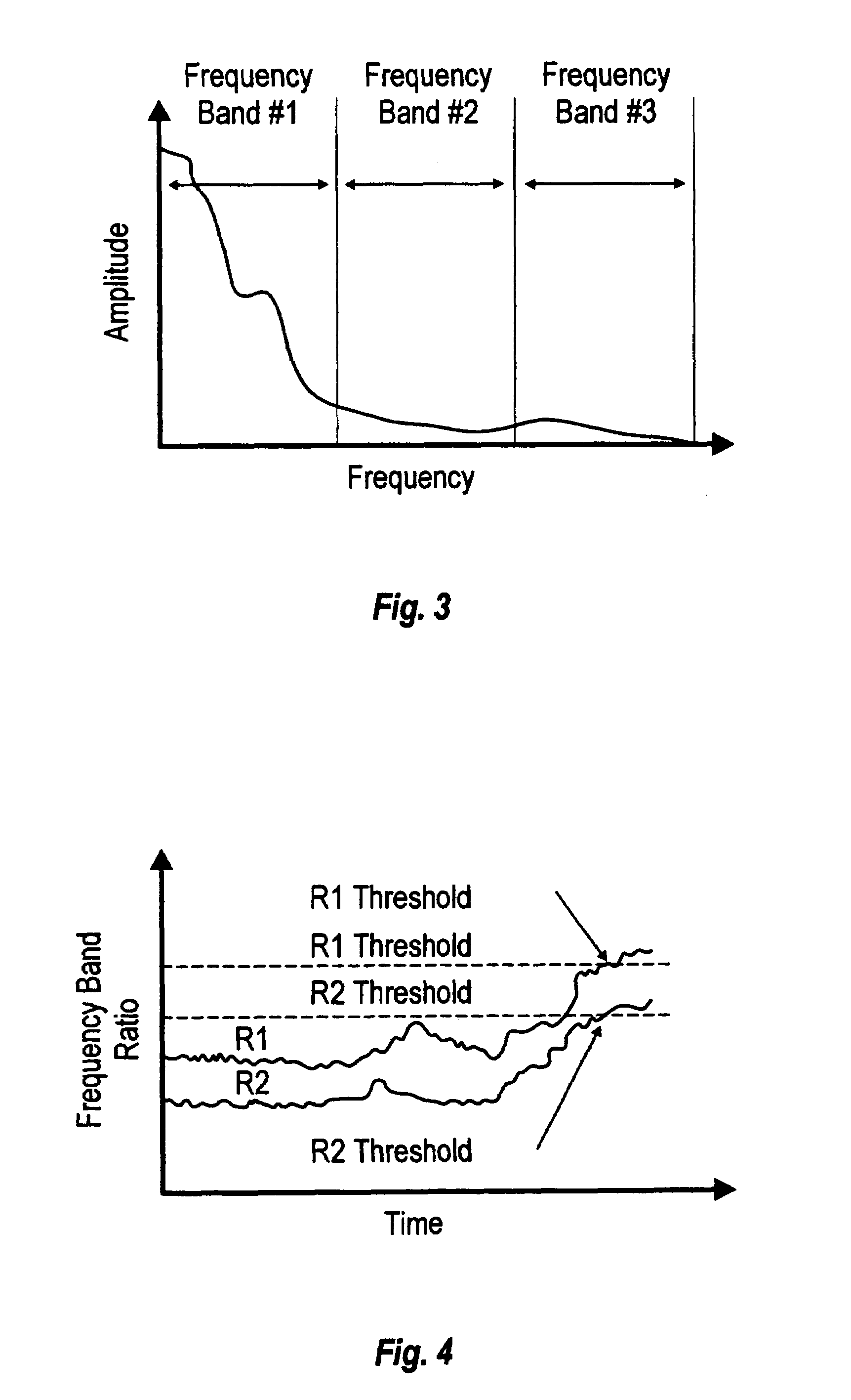
[0149]The sampling rate for most of the data recorded was 5000 hertz. Test data was recorded at sample rates of 5000, 10,000, 20,000 and 50,000 hertz. A frequency analysis showed that a very high percentage of the total strain gauge signal power was below 250 hertz. For this...


PUM


Abstract

A method and apparatus for signalling the surface operator about downhole conditions. Sensors located downhole collect data while drilling and the data is processed to determine bit failure, for example. When the sensor data indicates a failure, the pressure of drilling mud is varied using a valve on the downhole unit, and this pressure variance is indicated by a pressure gauge visible to the operator. This pressure change tells the operator a failure has been indicated.

Description

CROSS-REFERENCE TO OTHER APPLICATION[0001]This application claims priority from U.S. provisional applications 60 / 247,263, 60 / 246,681, 60 / 246,656 and 60 / 247,042, all filed Nov. 7, 2000 and all hereby incorporated by reference.[0002]The present application has some Figures in common with, but is not necessarily otherwise related to, the following application(s), which are commonly owned with and have the same effective filing as the present application, and which are all hereby incorporated by reference:[0003]Appl. Ser. No. 10 / 040,301 filed Oct. 26, 2001;[0004]Appl. Ser. No. 10 / 040,927 filed Oct. 26, 2001;[0005]Appl. Ser. No. 10 / 035,350 filed Oct. 26, 2001;[0006]Appl. Ser. No. 10 / 040,304 filed Oct. 26, 2001;[0007]Appl. Ser. No. 10 / 040,294 filed Oct. 26, 2001; and[0008]Appl. Ser. No. 10 / 040,928 filed Oct. 26, 2001.BACKGROUND AND SUMMARY OF THE INVENTION[0009]The present invention relates to systems, methods, and subassemblies for drilling oil, gas, and analogous wells, and more particu...

Claims


Application Information

Patent Timeline
Patent Type & Authority Patents(United States)
IPC IPC(8): E21B47/00E21B44/00E21B12/02E21B28/00E21B41/00E21B47/18
CPCE21B12/02E21B41/0085E21B44/00E21B47/18E21B47/185E21B2041/0028E21B47/22E21B2200/22
Inventor SCHULTZ, ROGER L.JESUS, ORLANDO DEOSBORNE, JR., ANDREW J.
Owner HALLIBURTON ENERGY SERVICES INC
Why Eureka
Try Eureka